-
Notifications
You must be signed in to change notification settings - Fork 39
DIY guide
Even though this is a DIY electronics project, no coding is required at all, and only a limited amount of soldering is needed. The D1 mini board (with the ESP8266 WiFi module) handles powering the chip via USB, and enables uploading the firmware over the same USB connection from PC or Mac.
Josh from @Budget Church Livestreaming has made a great tutorial, covering the main parts of the build process. Check out his video!
As I bought my parts of a small Danish website those links would be invalid for most people. Instead, here are some Amazon links to similar components (DISCLAIMER: I take no responsibility for the components you choose to buy, you do so at your own risk!).
-
D1 mini (ESP8266) - Make sure to get one with 4M Bytes of flash (not D1 mini lite with only 1M Byte flash!)
Optionally you can get the D1 mini pro (ESP8266) instead which should have better WiFi range as it has an external antenna. - RGB LED - Common Cathode - I was able to buy them separately at home, but on Amazon i can only find packs with 100 LEDs...
- Three 120 ohm resistors per unit. (120 ohm resistors is what I had laying around...)
- USB to Micro USB cable and a 5V power source (one per unit).
- And of cause solder and a soldering iron.
The circuit itself is quite simple, but the size of it can make the soldering process a bit tricky. Having something to hold the components in place while soldering is a great help.
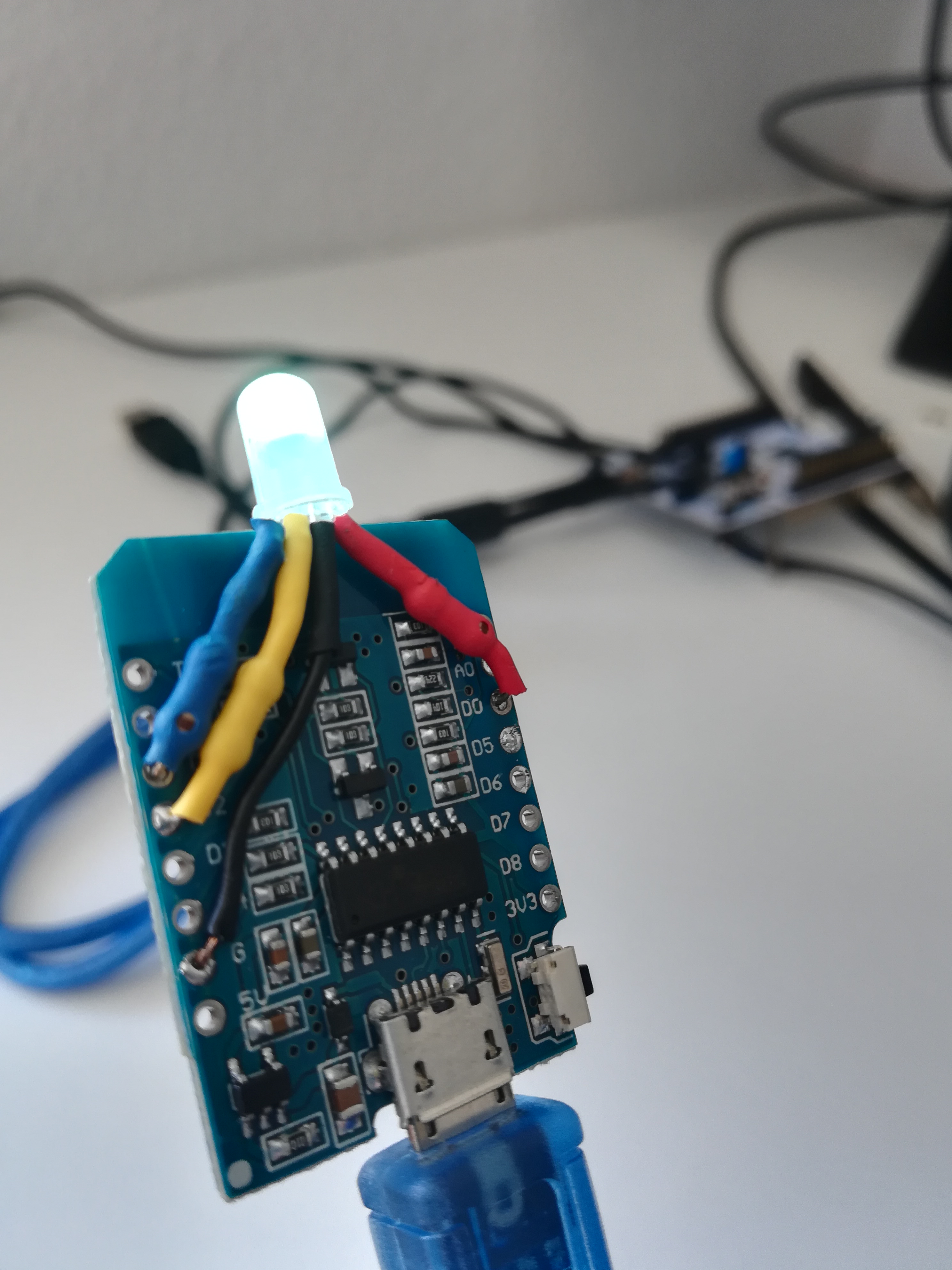
The LED has four pins - RED, GROUND, GREEN and BLUE - with the GROUND pin being the longest one. The pins for the colors needs to be connected with a resistor, or else the LED will burn out too soon as the voltage would be too high. To avoid shorts you should insulate the connections to the LED with eg. shrink flex or electrical tape.
Connecting it as explained in the below table makes is possible to not have to cross any wires on the back of the D1 mini to the LED, as shown on the picture (Yellow being the GREEN pin). (I used 120 ohm resistors i had laying around which lowers the voltage enough - I think the 430 Ohm resistors included in the LED packet linked above would lover the voltage too much, and make for a weak light, if not no light at all. However, I'm not an expert in this area, and haven't done any tests...).
| D1 mini pin | resistor | LED pin |
|---|---|---|
| D0 | 120 Ohm | RED |
| G | None | GROUND |
| D1 | 120 Ohm | BLUE |
| D2 | 120 Ohm | GREEN |

Support for a 2nd LED has later been added to the project. It can optionally be connected as described in the following table.
| D1 mini pin | resistor | LED pin |
|---|---|---|
| D4 | 120 Ohm | RED |
| G | None | GROUND |
| D5 | 120 Ohm | GREEN |
| D6 | 120 Ohm | BLUE |
Neopixels are also supported, and would be connected as such:
| D1 mini pin | LED strip pin |
|---|---|
| D7 | Data in |
| 5V | 5V |
| G | Ground |
With Neopixels, be aware of how many LEDs you connect, regarding performance impact and how much current they draw. Currently the limit is set to 1000 LEDs, which theoretically take 30ms to update each time, which is a lot when the ESP also needs time to process WiFi and tally data. The less LEDs the better performance, but as long as the WiFi stuff gets to run at least every 50ms it should be fine.
Regarding current, please do your own reseach, as many solutions, products and tutorials exists. Some say max 10 LEDs! My main problem is that I don't have a LED strip to test with myself.
If you have addressable LEDs other than Neopixels, that are compatible with the FastLED library, you can change that in the code manually. (look for FastLED.addLeds<NEOPIXEL, DATA_PIN>(leds, settings.neopixelsAmount)).
In order for the D1 mini to connect with your computer you need to install the following driver:
Try out the new Web installer if you use de described pin configuration, and don't need to change any of the code. In this case you can skip the Arduino IDE step.
Otherwise, press the arrow below, and flash the board through the Arduino IDE.
The Arduino IDE is used to program the D1 mini. You can download it for free at https://www.arduino.cc/en/Main/Software
Once the Arduino IDE is installed three things needs to be done before we can program the D1 mini.
In in order for the Arduino IDE to be able to program the D1 mini it needs a board manager to do so.
-
Open the Arduino IDE you just installed
-
Open the preferences window by selecting Files -> Preferences
-
Copy and paste the following link into the "Additional Boards Manager URLs:" field.
https://arduino.esp8266.com/stable/package_esp8266com_index.jsonThen close the preferences window.
-
Open the Boards Manager window in Tools -> Board:"board name" -> Boards Manager...
-
search for esp8266, select version
2.7.4, and click install. Once done, close the Boards Manager window.NOTE: using version
2.7.4is important if you want to use Neopixels. -
Select "LOLIN(WEMOS) D1 R2 & mini" in the list of boards through Tools -> Board:"board name" -> ...
-
Select "v2 Higher Bandwith" in the list of lwIP variants through Tools -> lwIP Variant:"variant" -> ...
Since support for Neopixels was added, the program needs the FastLED library.
- Open the Library Manager in Sketch -> Include Library -> Manage Libraries.
- Search for FastLED and click install. Once done, close the Library Manager.
Finally we need to download the the files containing the program for the tally light.
- Download the latest release here. Select Source code (zip) and extract the zip files once the download has completed.
- Open the Arduino sketch folder. By default created in Documents/Arduino on your computer by the Arduino IDE.
- Copy and paste the libraries and ATEM_tally_light folder from the download into the Arduino folder (A libraries folder might be there, in that case the content should merge. If not, copy the content of the libraries folder into the Documents/Arduino/libraries folder)
By now you should be all set to program the D1 mini by following these steps.
- Open the ATEM_tally_light.ino file with the Arduino IDE (placed in Documents/Arduino/ATEM_tally_light/ATEM_tally_light.ino)
- Check which COM ports ports are currently available in the Arduino IDE in Tools -> port -> list of COM ports (if none, don't worry)
- Connect the D1 mini to your computer with a usb cable, and select the new COM port that came up. You should now be connected to your board.
- Hit the upload button (2nd button, with an arrow pointing right) and wait for the upload to finish. This can take a few minutes and red text will be shown in the console at the bottom of the window. It might show a few warnings but this is normal. The important part is that a small LED on the D1 mini board should start blinking after a while, and the tally LED will flicker in red, while the console prints out how far it is with uploading the program. It will tell you when it's done in the blue bar above the console. If it fails the bar will turn orange and give an error message.
Note: You can reset the WiFi settings of the chip by selecting "Sketch + WiFi Settings", and all settings by selecting "All Flash Contents" in the list under Tools -> Erase Flash: "setting" -> ...
Remember to select "Only Sketch" again, so that future uploads doesn't erase settings unintentionally.
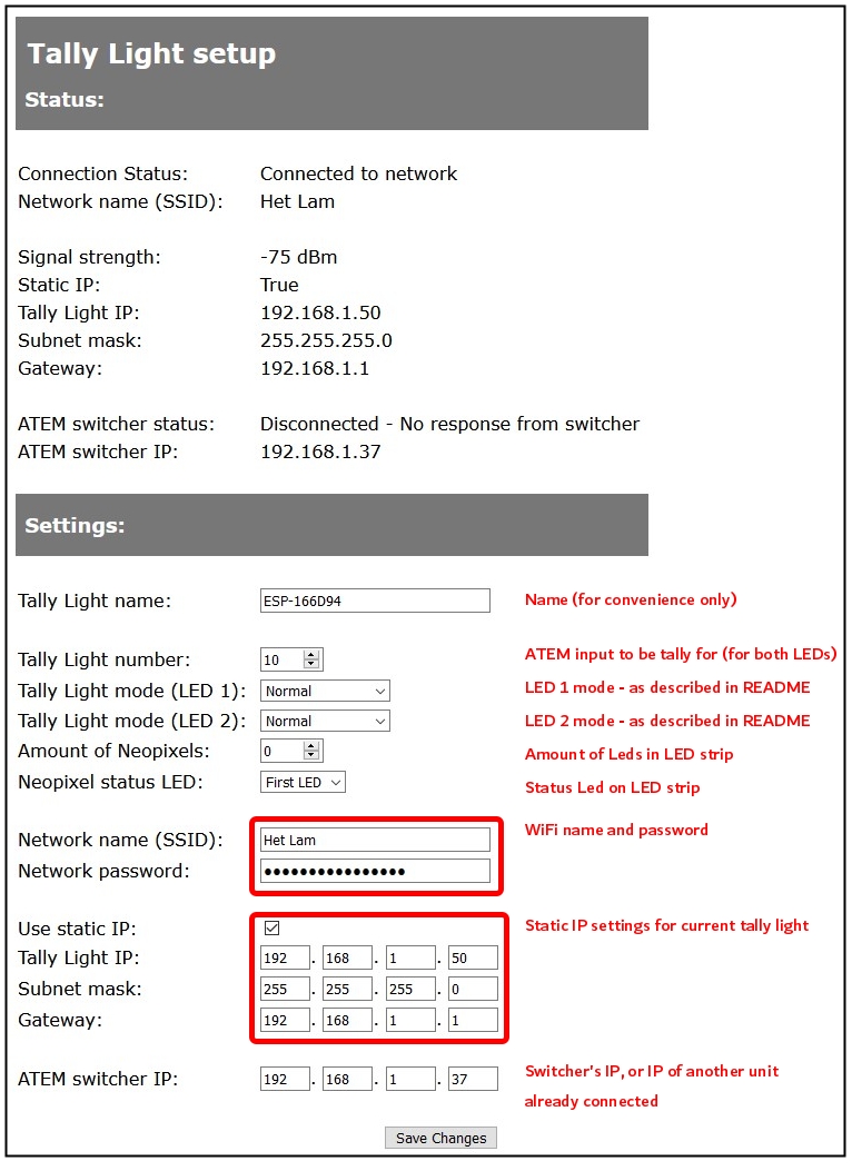
Once the program is uploaded to the ESP8266 the setup is done with a webpage it serves over WiFi where you are able to see status details, and perform the basic setup.
-
Wait for the LED to turn white (if it turns pink instead, see Unable-to-access-setup-page?)
-
Connect to the network named "Tally light setup" and open 192.168.4.1 in a browser.
-
Set tally name, number & mode, WiFi name & password, IP addresses for the tally light, and the IP address of your switcher or another tally unit already connected.

WARNING: Do NOT leave the tally lights IP addresses static with values 255. A fresh chip will result in tallyNo and IPs being set to 255, which gives for an invalid configuration resulting in you being unable to reach the setup page. Preferably you set a valid static IP, which you also add in your router, so that it doesn't collide with other devices. Disabling static IP will make it harder for you to change settings later on, as you need to find the IP address via the router first.
-
Hit Save Changes. You should get a success message. Wait for 5-10 seconds whereafter it reboots with the new settings applied.
You can now access the setup page by entering the IP address assigned to the tally light while connected to the same network.
Once set up correctly, it will automatically connect to your WiFi and switcher when powered on.
Congratulations, you're all set up! 🎉
Consider supporting by bying me a coffee
To get around the ATEM switchers' connection limit of 5-8 clients, v2.0 introduced Tally Server functionality. This makes the system only require one connection from the switcher. An example setup is shown in the diagram below, where arrows indicate the direction of tally data from swtcher/tally unit to client tally unit.

NOTE: As this brings a lot of flexibility with how to connect the units, bear in mind that the ESP8266 isn't that powerful, and is limited to 5 clients each. (In some cases 5 might even be too many).
The "Tally light setup" network will be available if the tally light is unable to connect to WiFi, which is signalled with the light being white. When it's connected to a network, you need to access the setup page through it's assigned IP address. There are multiple options if you don't know the IP address.
- Locate the IP address through you routers client list. See your routers manual for how to.
- Connect the tally light to your computer, and open the Arduino IDE. Select the correct COM port, and open the serial monitor (top right button). Select "115200 baud" bottom right in the window, and press the reset button on the tally light. Once connected to WiFi it will print the IP settings.
- Reset the WiFi settings.
If the IP settings are invalid, you'd need to either move the tally light out of range of your network or reset the WiFi settings in order to access the "Tally light setup" network.
To reset the WiFi settings select "Sketch + WiFi Settings" in Tools -> Erase Flash: "setting" -> ... and reupload the program.

