-
-
Notifications
You must be signed in to change notification settings - Fork 0
PCB Rev. 1
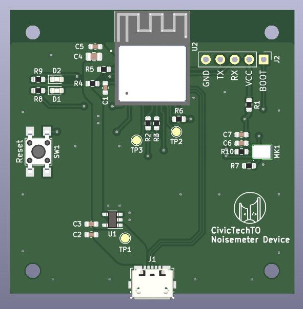
The first revision of the noisemeter PCB was designed as a prototype that integrates the ESP32 microcontroller and I2S microphone on a single circuit board. As a prototype, extra IO pins were brought out as test pads, two LEDs were included for status and diagnostic indications, and an easy-to-use 0.1" header exposed the ESP32's serial port for programming. The USB data pins were also routed to the USB port in case their functionality was desired.
Five "rev1" boards were initially ordered. Testing proved the design to be effective, leading to the "rev2" board design that followed.
This page will describe the steps required to prepare and program a new device PCB.

The are two connections on the board that can be used to program the ESP32 microcontroller:
- The serial header (labeled "J2")
- the micro-B USB port
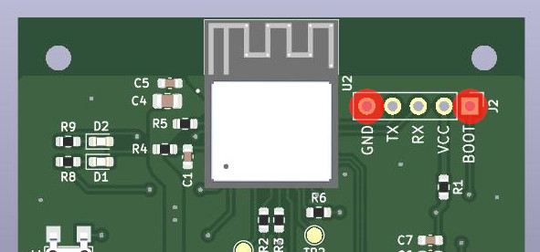
To use the serial header, connect a USB-to-serial adapter to the GND, TX, and RX pins on J2. Note that the adapter's TX should go to the device's RX pin and vice versa. Baud rate is 115,200.
The VCC pin on J2 can be used to power the device with 3.3V. Double-check that your adapter is not providing 5V -- applying >3.3V could destroy the device!
The BOOT pin connection is described below.
Since the ESP32's USB data lines were routed to the USB port, it is possible to communicate with and program the ESP32 via USB. After making the BOOT pin connection described below, plugging the device into your computer with a USB cable will both power up the device and present a USB/serial connection.

For the initial USB port programming or for any serial header programming, the BOOT pin on J2 must be grounded before the board is powered up. A simple wire will work; you may also prepare a serial header connector that bridges the GND and BOOT pins.
-
Install the Arduino IDE and follow these instructions to get support for the ESP32 microcontroller.
-
Under "Tools" > "Board: " > "ESP32 Arduino", select "ESP32C3 Dev Module".
-
Compile the sketch, located in this repo at
/src/esp32/v1/proj-noisemeter-device-esp32-v1. -
Either connect the board via USB to the computer (with BOOT grounded) or plug in your USB-to-serial adapter. Under "Tools" > "Port: ", select the device or adapter's port.
-
Upload the sketch. Once finished, disconnect the board from power before reconnecting it to run the new firmware.
After the initial programming, the serial header can be avoided: the device's logs will print out over its USB connection, and future firmware uploads can be done over USB without grounding BOOT.