-
Notifications
You must be signed in to change notification settings - Fork 52
prelecture_07_conductors_and_capacitance
- Today will extend our study of electric potential to
- Conductors
- Capacitance
- We will introduce this topic
- Last time we introduced Electric Potential
- [\Delta V_{A \rightarrow B} = -\int\limits_{A}^{B}{ \vec E \cdot d \vec l}]
- All example shown had fixed charge distrobutions, today we will introduce conductors without a fixed charge distrobution. * Conductors where the charges are free to move
- After discussing non-uniform charge distrobution in a conductor, we go on to discuss capacitance
- Specifically we discuss parallel plates
- [C \equiv \frac{ Q}{ \Delta V}]
- Field betwee plates [E = \frac{ Q}{ \varepsilon_0 A}]

- [V_B - V_A = -\int\limits_{A}^B}{ \vec E \cdot d \vec l}]
- [V_B - V_A = 0]
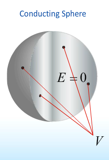
- Since [\vec E = 0] everywhere within the conductor
- This implies that the entire conductor it self is an equipotential

- When the conductor is circularly symmetric, the field lines are perpendicular to the surface

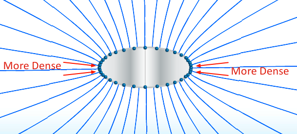
- When we change the shape such that it is no longer circularly symmetric the charge density redistributes such that we have varying points of charge density

A solid elliptical conductor with a net charge [Q] is surrounded by a hollow spherical conductor with net charge [-Q]. Points [a] and [c] are on the outer surface of the inner conductor, and points [b] and [d] are on the inner surface of the outer conductor as shown.
Compare [V_{ab}], the magnitude of the potential difference between points [a] and [b], to [V_{cd}], the magnitude of the potential difference between points [c] and [d].

- [V_{ab} = V_{cd}]
- Since each conductor is an equipotential, the potential difference between any point on the inner conductor and any point on the outer conductor has to be the same.

-
Consider two conducting spheres which are seprerated by a large distance and have radius' [R_A] and [R_B = 4 R_A]
-
Calculating the potential at the surface of [A]
- [V_A = -\int\limits_{\infty}^{R_A}{ \vec E_A \cdot d \vec l}]
- [V_A = -\int\limits_{\infty}^{R_A}{ k \frac{ Q}{ r^2} d r}]
- [V_A = k \frac{ Q}{ R_A}]
-
Repeat for sphere [B]
- [V_B = k \frac{ Q}{ R_B}]
- [V_B = k \frac{ Q}{ 4 R_A}]
- [V_B = \frac{ 1}{ 4} V_A]

- What if we connect the sphere's via a thin wire?
- The charges will in essence become a single conductor
- Their charges will flow until the come to the same potential.
- [V_A = V_B]
- [k \frac{ Q_A}{ R_A} = k \frac{ Q_B}{ R_B}]
- [k \frac{ Q_A}{ R_A} = k \frac{ Q_B}{ 4 R_A}]
- [\frac{ Q_A}{ R_A} = \frac{ Q_B}{ 4 R_A}]
- [Q_A = \frac{ Q_B}{ 4}]
- [ 4 Q_A = Q_B]
- [ Q_A + Q_B = 2 Q]
- [ Q_A = \frac{ 2}{ 5} Q]
- [ Q_B = \frac{ 8}{ 5} Q]
- Note
- Even though sphere [B] has four times the charge of sphere [A] the charge density on sphere [A] is still larger.
- [4 Q_A = Q_B]
- [4 \sigma_A Area_A = \sigma_B Area_B ]
- [4 \sigma_A 4 \pi R_A^2 = \sigma_B 4 \pi R_B^2 ]
- [4 \sigma_A R_A^2 = \sigma_B R_B^2 ]
- [4 \sigma_A R_A^2 = \sigma_B (4 R_A)^2 ]
- [4 \sigma_A R_A^2 = \sigma_B 4^2 R_A^2 ]
- [4 \sigma_A = \sigma_B 4^2]
- [\sigma_A = \sigma_B 4]
- [\sigma_A = 4 \sigma_B]
- Uncharged spherical conducting shell with a positive charge placed in the cavity.

- The presence of the positive charge will cause the charges in the conducting
shell to move so as to preserve the zero electric field in the center
* QUESTION: This was an uncharged spherical shell, why is it worded this way in the prelecture??
- Consequently both surfaces of the shell receive an induced charge.
- [Q_{inner} = -q]
- [Q_{outer} = q]

- Should the charge at the center of the sphere move to the right
- Inner surface charge distribution changes accordingly.
- Outer surface charge distribution stays the same.
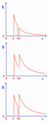
Consider a charged solid conducting sphere of radius [a] inside an uncharged hollow conducting sphere having inner radius [b] and outer radius [c], as shown.
Which of the following graphs best describes the magnitude of the electric field as a function of distance [r] from the center of the sphere?


- A
- According to Gauss law the [E]-field will simply diminish as [\frac{ 1}{ r^2}] when is [r > a]. Since the outer conducting shell is uncharged it does not contribute to [E] in any way other than ensuring that [E = 0] inside the shell itself (i.e., for [b < r < c]).
- We just explored what happens when we move a charge around the inside of a conducting spherical shell.

- Now we will explore what happens when you do the same outside the shell.

-
Similarly the charge distribution on the outer shell will act accordingly to the position of the outer charge [q].
-
Now consider if we create a cavity within the solid conductor

- Similarly again, the charge on the inner cavity remains unchanged by presence of the charge outside the conducting shell.
- The inner charge field of the conducting sphere always remains zero and the charges position them selves in such a manor to act accordingly.

- Let
- [\vec E] be the electric field between the plates
- [\Delta V] non-zero potential difference which develops as a result of this field.
- Since
- [E \propto Q]
- Then
- [\Delta V \propto Q]
- So we define the capacitance to be
- [C \equiv \frac{ Q}{ \Delta V}]
- The units of capacitance are Coulomb per Volt which is a Farad
- [ F = \frac{ C}{ V}]

- Let
- [A] be the surface area of the conducting plates
- [d] be the distance between the plates
- [L] be the edge lengths of the plates
- [\vec E] be the electric field created between the plates
- [ d << L]
- Given
- The magnitude of the [E] field created separately
- [E_{Top Plate} = \frac{ 1}{ 2} \frac{ \sigma}{ \varepsilon_0}]
- [E_{Bottom Plate} = \frac{ 1}{ 2} \frac{ \sigma}{ \varepsilon_0}]
- [E_{Top Plate} = \frac{ 1}{ 2} \frac{ Q}{ \varepsilon_0 A}]
- [E_{Bottom Plate} = \frac{ 1}{ 2} \frac{ Q}{ \varepsilon_0 A}]
- The magnitude of the [E] field created separately
- Then
- Since directions of their fields is the same, we determine that
- [E = \frac{ 1}{ 2} \frac{ Q}{ \varepsilon_0 A}]
- Since directions of their fields is the same, we determine that
- Now looking for the potential difference in [C \equiv \frac{ Q}{ \Delta}{ V}]
- [\left|\Delta V\right| = \int\limits_{bottom}^{top}{ \vec E \cdot d \vec l}]
- [\left|\Delta V\right| = \int\limits_{bottom}^{top}{ \frac{ Q}{ \varepsilon_0 A} d y}]
- [\left|\Delta V\right| = \frac{ Q}{ \varepsilon_0 A} \int\limits_{bottom}^{top}{ d y}]
- since [\vec E] is a constant along this path
- [\Delta V = \frac{ Q}{ \varepsilon_0 A} d]
- [C = \frac{ Q}{ \Delta V} = \frac{ \varepsilon_0 A}{ d}]
- Capacitance for Parallel-Plates
Two parallel plates carry equal and opposite charge [Q]. The potential difference between the two plates is measured to be [V_0]. An uncharged conducting plate (the green thing in the picture below) is slipped into the space between the plates without touching either one, and the potential difference between the two plates in this final configuration is measured to be [V_1].
Compare [V1] and [V0].

- [V_1 < V_0]
- The potential difference is given by the integral of [E \cdot d \vec l] from one plate to the other. The electric field in the extra conductor is zero, and the electric field in the rest of the region between the plates is the same as it was before the conductor was inserted. The total integral of is therefore smaller with the conductor in place since the integrand is zero for the part of the path inside the conductor.

-
Let
- [+q] be the charge of the top plate
- [-q] be the charge of the bottom plate
- [\vec E] the charge field
- [V] be the potential difference
- QUESTION: why isn't this [\Delta V]
- [d q] is the next increment charge
- [d W] the work required to move the next increment charge from the bottom plate to the top.
-
It follows that
- [d W = (dq E) d]
- [d W = d q \frac{ V}{ d} d]
- [d W = d q V]
- [d W = V d q ]
- [d U = V d q ]
- Holds true for any geometry as it represents the change in potential energy
- [U = \in{ d U} = \int\limits_{0}^{Q}{ V d q} ]
- [U \int\limits_{0}^{Q}{ V d q} ]
- [U \int\limits_{0}^{Q}{ \frac{ q}{ C} d q} ]
- [U \int\limits_{0}^{Q}{ \frac{ q}{ C} d q} = \frac{ 1}{ 2} \frac{ Q^2}{ C} ]
-
Therefore
- [U = \frac{ 1}{ 2} Q V]
- [U = \frac{ 1}{ 2} \frac{ Q^2}{ C}]
- [U = \frac{ 1}{ 2} C V^2]
- Since
- [U = \frac{ 1}{ 2} C V^2]
- where
- [V = E d]
- [C = \frac{ \varepsilon_0 A}{ d}]
- where
- [U = \frac{ 1}{ 2} \frac{ \varepsilon_0 A}{ d}( E d)^2]
- [U = \frac{ 1}{ 2} \frac{ \varepsilon_0 A}{ d} E^2 d^2]
- [U = \frac{ 1}{ 2} \varepsilon_0 A E^2 d]
- [U = \frac{ 1}{ 2} \varepsilon_0 E^2 A d]
- where [Ad] is the volume between the plates
- [\frac{ U}{ A d} = \frac{ 1}{ 2} \varepsilon_0 E^2]
- [\frac{ U}{ A d} = \frac{ 1}{ 2} \varepsilon_0 E^2]
- [u \equiv \frac{ U}{ A d} = \frac{ 1}{ 2} \varepsilon_0 E^2]
- where [u] is the energy density between the plates
- [U = \frac{ 1}{ 2} C V^2]
- Energy Density
- [u = \frac{ 1}{ 2} \varepsilon_0 E^2]
- Charges withing a conductor will always move as to create a zero electric field

- The electric field at the surface of a conductor is always perpendicular to that surface.

-
Capacitance formed between do parallel plates of a conductor is defined as
- [C \equiv \frac{ Q}{ \Delta V}]
-
Energy is stored between the electric plates
- [u = \frac{ 1}{ 2} \varepsilon_0 E^2]
- Energy Density
- [u = \frac{ 1}{ 2} \varepsilon_0 E^2]
-
Energy Stored in Capacitors
- [U = \frac{ 1}{ 2} Q V]
- [U = \frac{ 1}{ 2} \frac{ Q^2}{ C}]
- [U = \frac{ 1}{ 2} C V^2]