-
Notifications
You must be signed in to change notification settings - Fork 52
prelecture_10_kirchoffs_rule
Kurt Robert Rudolph edited this page Jun 28, 2012
·
8 revisions
- Start with a brief overview of the devices we will using
- Switch
- Battery
- Capacitor
- Resistor
- Switch
- Then we will introduce Kirchoff's Rule
- [\sum \Delta V_n = 0]
- any closed loop
- [\sum I_in = \sum I_out]
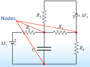
- at any node
- [\sum \Delta V_n = 0]
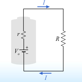
- Close by modeling a real battery as an ideal battery in series
- Battery
- Maintain a constant potential difference across their terminals
- sometimes this potential difference is referred to as the EMF
- [EMF \equiv \varepsilon = V_b]

- Maintain a constant potential difference across their terminals
- Capacitors
- Capacitors store charge
- [V_C = \frac{ Q}{ C}]
- the voltage drop accross capacitors is equal to excess charge [Q] on one plate divided by [C] it's capacitance.
- We speak about capacitors in terms of the rate of change across it's plates.

- Resistors
- The voltage drop across resistors is proportional to current that flows through it.
- [V_R = I R]

- Switch
- Used to add or remove other devices from the circuit.
- When the switch is open no current passes through it when the switch is close current passes freely through it. and the voltage across the switch is zero.

- Used to add or remove other devices from the circuit.
- Voltage Rule
- [\sum \Delta V_n = 0]
- If you start on any point in a circuit and follow that around a complete loop the net change in the electric potential is zero.

- Current Rule
- [\sum I_{in} = \sum I_{out}]
- Essentially a statement of charge conservation, at any node in a circuit a place where two or more wires meet, the sum of the currents flowing in is equal to the sum of the currents flowing out.

- In order to apply these two rules to circuits we must first address the issue of sign convention. In particular we need to address the conventions for the direction of current flow and the sign in which the voltage changes.
- One loop circuit

- It doesn't matter which way you go ultimately the change in potential is zero.
- For historical reason we will go clockwise around the loop
- we define [\Deslta V_{R_1} = + V_{R_1}] to be positive across resistors.
- Again looking at a single loop

- As we move around the loop from point a to point b
we encounter a voltage drop. Which is equal to the
product of the current and the resistance.
- [\Delta V_{R_1} = + I R_1]
- [\Delta V_{R_2} = + I R_2]
- [\DELTA V_{batter} = - V_b]
- Hence [\sum \Delta V_n = I R_1 + I R_2 + (- V_b) = 0]
- As expected we find that [I = \frac{ V_b}{ R_1 + R_2}] * This follows that the direction is clockwise.
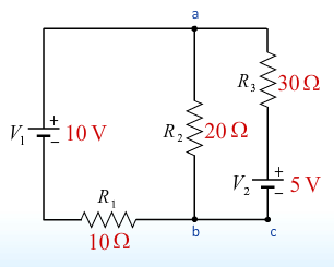
- We now look at a two loop example.

- Analyzing the loops we find three equations and three unknowns.
- [I_1 + I_2 = I 3] kirchoff's current rule
- [I_3 R_3 + V_2 + I_1 R_1 - V_1 = 0] outer loop
- [-I_2 R_2 + I_1 R_1 - V_1 = 0]

Consider the circuit shown above. Which of the following statements best describes the current flowing in the blue wire connecting points [a] and [b].

- No current flows between [a] and [b]
- Because the halves of the circuit above and below the blue wire are identical, the voltage at [a] (and hence also at [b]) is just half the voltage of the battery. This means that the current in the upper resistor labeled R is the same as the current in the lower resistor labeled [R], which by Kirchhoff's Current Rule tells us that the current in the blue wire it self must be zero. Exactly the same argument can be made at point [b].
- Thus for we have considered batteries to be ideal, i.e. we have assumed that batteries produce a constant potential difference across their terminals independent of the current being drawn.
- Now we will consider real batteries where the voltage across the terminals can decrease if a large enough current is being drawn from the battery.
- Example

- [I = \frac{ V_0}{ R + r} ]
- EMF of the battery divided by the total resistance.
- In turn the voltage which appears at the terminals is as follows
- [V_b = V_0 - I r]
- [V_b = V_0 - \frac{ V_0 r}{ R + r}]
- [V_b = V_0 \frac{ \frac{ R}{ r}}{ 1 + \frac{ R}{ r}}]
The 'real' batteries and the resistors in both cases illustrated above
are identical. In which case is the voltage across the terminals of
the battery closest to the ideal battery voltage [V_0]?

- The voltage across the terminals of the battery is closest to ideal in Case A
- The current supplied by the battery in Case A is smaller than in Case B since the resistance of the external load in Case A is twice as big as in Case B. If the current supplied by the battery is smaller, the voltage drop across the internal resistance of the battery will also be smaller, and hence the voltage across the terminals of the battery will be closer to the ideal battery voltage.
- Kirchoff's Rules
- Voltage Rule [\sum \Delta V_n = 0]
- any closed loop
- Current Rule [\sum I_{in} = \sum I_{out}
- at any node
- Voltage Rule [\sum \Delta V_n = 0]