Test bench with rotary encoder for U8g2 version

The following basic configuration can be prepared in order to follow along with the examples provided with the library.
Test bench for U8g2 version of library consists of 128x64 OLED display and rotary encoder with built-in button used to navigate through the menu.
- Arduino UNO or compatible
- Rotary encoder with built-in button (e.g.)
- 128x64 OLED display based on SH1106 chipset or compatible with I2C interface (e.g.)
Schematic is simple. Three signal terminals of rotary encoder (two for rotation direction, one for button) are connected to the input pins of Arduino initilized with INPUT_PULLUP mode with internal pullup resistors activated (alternatively it is possible to connect terminals using external pullup 10kOhm resistors and INPUT mode). You may wish to implement additional debounce filtering to minify chances of false readings at the moment of button press (or try to increase value of the debounceDelay parameter during KeyDetector initialization).
Connect I2C signal lanes of the display to corresponding pins of Arduino. Connect power and ground as required by your display. In case of a particular display used in this example, it is powerd by 3.3V and is compatible with 5V logic, so it is possible to wire it directly to Arduino UNO R3 without the need for power/logic level shifting.
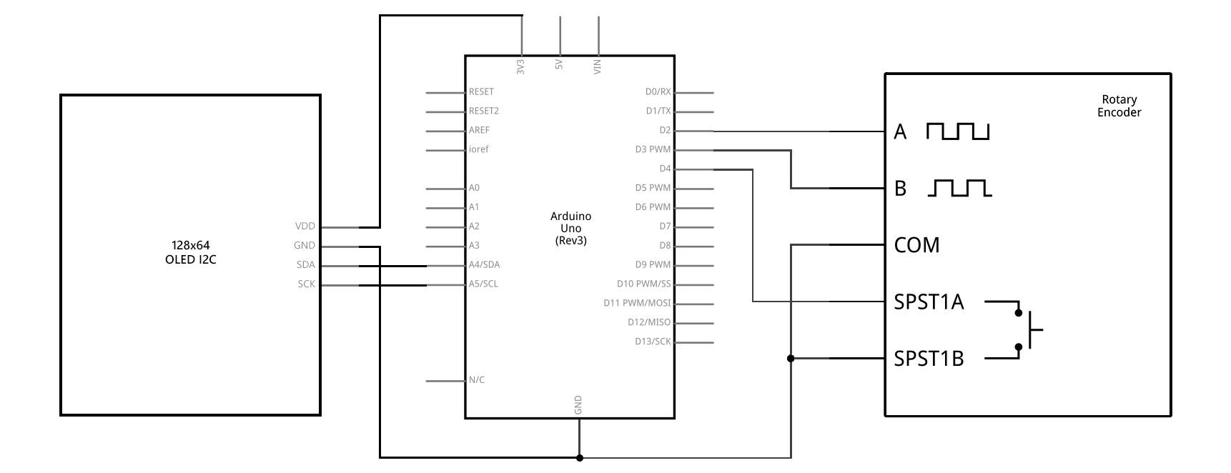
Connect channel A output (also called channel 1, CLK, etc.) of encoder to Arduino input pin 2, channel B output (also called channel 2, DT, etc.) to pin 3, first button output (usually called SW) to pin 4. Connect second button output (if present) and ground terminals of encoder to ground. Connect power terminal (if present) to 5V or 3.3V (depending on Arduino board being used).
Note that it may be required to swap channel terminals of encoder if direction of rotation is determined incorrectly.
Connect SDA pin of display to SDA pin of Arduino (A4 on Arduino UNO R3), SCK pin of display to SCL pin of Arduino (A5 on Arduino UNO R3). Provide power to display.

This test bench is compatible with the rotary encoder based U8g2 examples supplied with the GEM library (if not stated otherwise).
After compiling and uploading sketch to Arduino, wait while OLED screen boots and menu is being initialized and drawn to the screen. Then start rotating knob of the encoder and pressing its button to navigate and interact with the menu. The following control scheme is implemented.
| Encoder | Key identifier | Action |
|---|---|---|
| Rotate CW | GEM_KEY_DOWN |
Navigate down through the menu items list, select previous value of the digit/char of editable variable, or next option in select |
| Rotate CCW | GEM_KEY_UP |
Navigate up through the menu items list, select next value of the digit/char of editable variable, or previous option in select |
| Rotate CW while pressed | GEM_KEY_RIGHT |
Navigate through the link to another (child) menu page, select next digit/char of editable variable, execute code associated with button |
| Rotate CCW while pressed | GEM_KEY_LEFT |
Navigate through the Back button to the previous menu page, select previous digit/char of editable variable |
| Short press | GEM_KEY_OK |
Toggle bool menu item, enter edit mode of the associated non-bool variable, exit edit mode with saving the variable, execute code associated with button |
| Long press | GEM_KEY_CANCEL |
Navigate to the previous (parent) menu page, exit edit mode without saving the variable, exit context loop if allowed within context's settings |
See description of the specific example for details.