-
Notifications
You must be signed in to change notification settings - Fork 0
Hardware construction
In this section, we will give you a tutorial on how to make your own SenseStack modules. Wiring and connection inside the sensors modules totally depend on each sensor type which is not included in this document.

- Stackable modules.*
- Provides quick and easy way to make a prototype of the stackable modules.
- Fully 3D printed enclosure design. The design is adjustable to fit different form factors.
- Custom PCBs for both main module and sensor modules, designed to abstract the connections between MCU and other hardware inside the module.
*Due to the limitations from power input and physical structure, modules can stackable up to 10 modules.
SenseStack has two modules type. First, the main module, contains ESP32 microcontroller which acts as the main processor, along with manage the communication between server and sensor modules. Second, the sensor module, it operates by Arduino Nano which allows users to integrate any sensors to the SenseStack system.
To build an enclosure for modules, 3D-printer is mandatory. Ready-to-print files (.stl) and Fusion 360 design file (.f3z) can be found here. Enclosures body (Bottom part) are required support material, recommend print material is PLA with 20% infill and a layer height of 0.2 mm. We have printed all parts with Flashforge Dreamer.
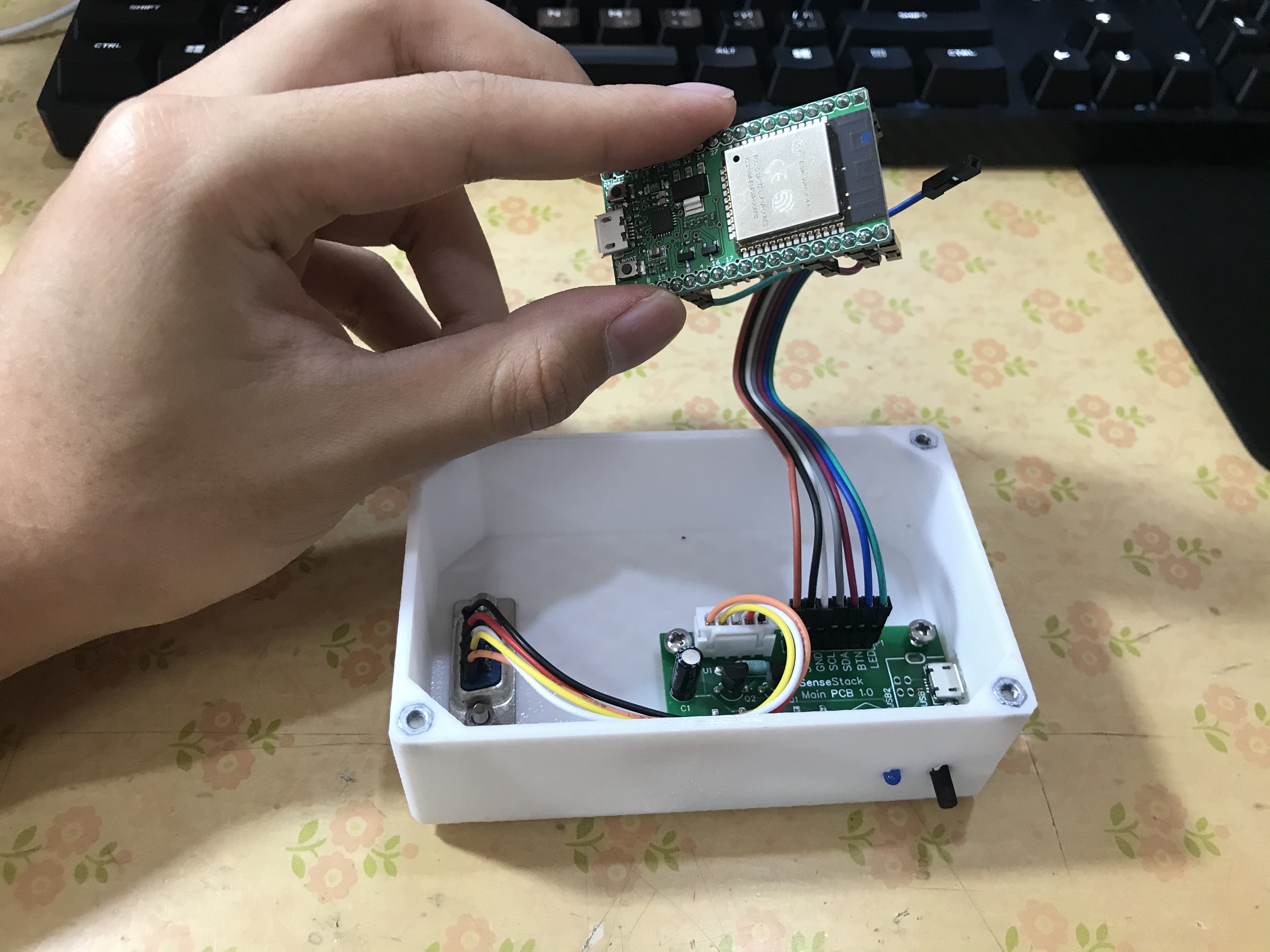
The main module is designed to be compatible with any ESP32 development board, for instance, SenseStack’s main PCB. A main PCB exposes five headers: 5V and 3.3V power line, SDA, SCL, a push button and an LED. The ESP32 development board is connected to the main PCB using jumper wires.
- ESP32 Development Board
- SenseStack Main PCB
- DB-9 Male connector
- 3D printed enclosure and lid for main module
- 6 pcs M3 Nut
- 6 pcs M3 10 mm countersunk screw
- Clean and finish the 3D printed parts with abrasive tools (if necessary).
- Solder electronic parts to SenseStack Main PCB.
- Mount a DB-9 male connector (with JST connector soldered to it), and SenseStack Main PCB to the 3D printed enclosure, with M3 screw and nut.
- Connect ESP32 Development Board to SenseStack Main PCB with jumper wire,
- Connect JST connector from the DB-9 connector to the header on SenseStack Main PCB.
- Flash the main module firmware to the ESP32 Development Board.
- Close the lid and mount it using countersunk M3 screw.

This type of module enables SenseStack to use any sensors that are compatible with Arduino. The main purpose of sensor module is to convert different protocols from different sensors to SenseStack standard protocol.
- Arduino Nano Development Board
- SenseStack Sensor Module PCB
- A sensor unit of choice
- DB-9 Male connector
- DB-9 Female connector
- 3D printed enclosure and lid for sensor module
- 10 pcs M3 Nut
- 10 pcs M3 10 mm countersunk screw
- Clean and finish the 3D printed parts with abrasive tools (if necessary).
- Solder electronic parts to SenseStack Sensor PCB.
- Attach Arduino Nano microcontroller to SenseStack Sensor PCB.
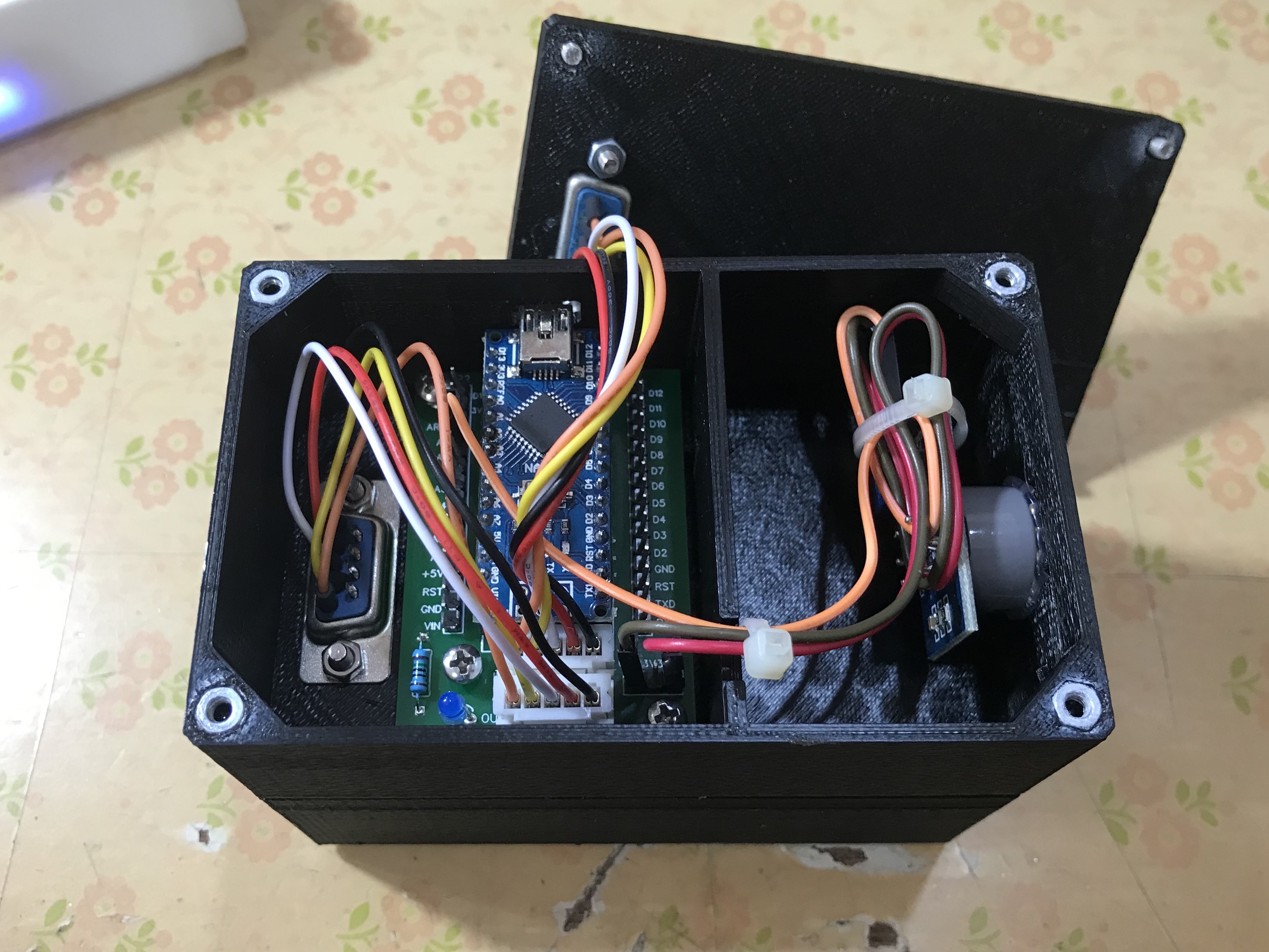
- Mount a DB-9 male connector to the bottom enclosure, and a DB-9 female con- nector to the lid of sensor enclosure, both with JST connector soldered to it. Mount SenseStack sensor PCB to the enclosure as well, all using M3 screw and nut.
- Connect two JST connectors from both the male and female DB-9 connectors to the header on the SenseStack sensor PCB.
- Connect sensor to the header on the SenseStack Sensor PCB, using jumper wires.
- Flash sensor firmware to the Arduino Nano Development Board.
- Close the lid and mount it using countersunk M3 screw.

All modules need to be flashed with appropriate firmware, detailed instruction about firmware flashing can be found at Quick start guide. After the configuration process was done, sensors modules can be simply added, swapped or removed on-the-fly without the need of any reconfiguration or firmware reflashing.