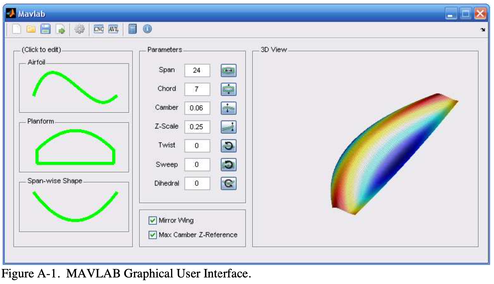
Repo for mavlab PARAMETRIC SOFTWARE TOOL FOR THE DESIGN AND MANUFACTURING OF MICRO AIR VEHICLES.
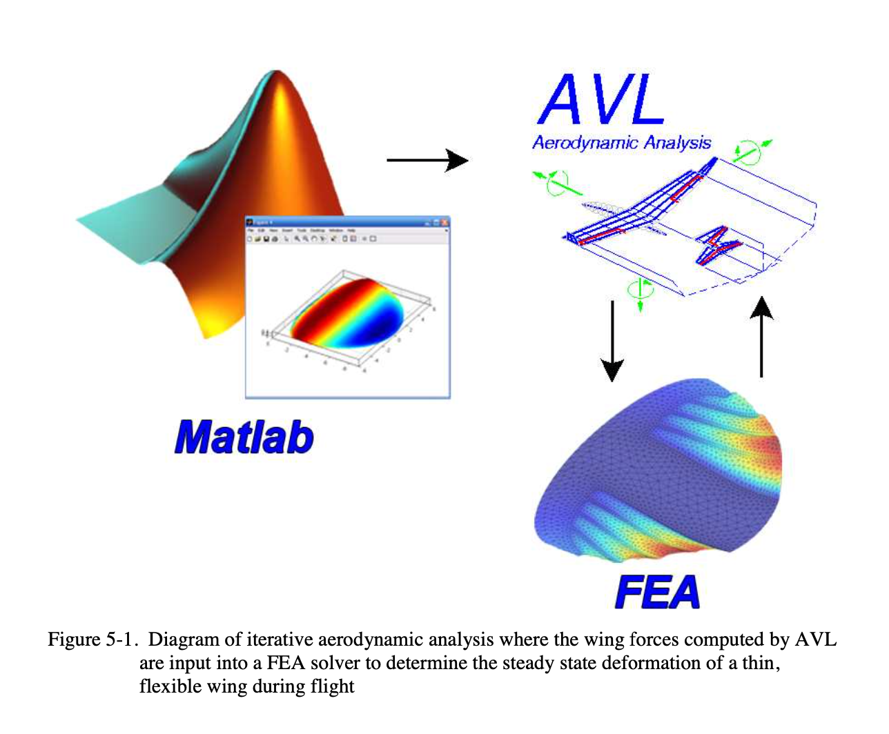
This includes tools for computer aided design (CAD), aerodynamic analysis (via AVL), finite element analysis (FEA) and computer aided machining (CAM).
Note: This was last tested in Matlab R2006b. YMMV on later versions.
- Clone Repository
git clone https://github.com/foomoon/mavlab.gitIn Matlab, navigate to the mavlab "/src/dc" directory
installmavlabOnce mavlab paths are correctly added through the installmavlab script, the GUI can be initiated with the following command
mavlabMavlab can be run without the GUI using the dcBuild function. This requires the construction of a "wing" struct object to be input into dcBuild. See below for more details. Take a look in the "/src/dc/save" folder for *.mat files which can be loaded into the workspace as examples to work from.
Below is a brief summary of the primary files and functions
| file | Description |
|---|---|
| mavlab.m | Entrance function for MAVLAB called at command prompt |
| dcAVL.m | GUI for running AVL CFD |
| dcBuild.m | Main function for generating wing geometry from parameters |
| dcCNC.m | GUI for creating a CNC toolpath for airframe geometry |
| dcGetFoil.m | GUI for creating/modifying an airfoil |
| dcGetPlan.m | GUI for creating/modifying the wing planform |
| dcGetSpan.m | GUI for creating/modifying the span-wise shape of a wing |
| dcLoadfoil.m | Supporting figure file for dcLoadfoil.m |
| dcMain.m | GUI main function for MAVLAB |
| dcSurf.m | Plot airframe geometry from parameter data |
| dcAVL.fig | Supporting figure file for dcAVL.m |
| dcGetFoil.fig | Supporting figure file for dcGetFoil.m |
| dcGetPlan.fig | Supporting figure file for dcPlanFoil.m |
| dcGetSpan.fig | Supporting figure file for dcGetSpan.m |
| dcLoadfoil.fig | GUI for loading an airfoil into the database from a text file |
| dcMain.fig | Supporting figure file for dcMain.m |
The following outlines the basic structure of MAVLAB wing file auto-generated by MAVLAB. Descriptions of what each parameter does are in my thesis. Each parameter is stored in a structure variable, in this case named “wing.” See Matlab documentation on how to create/modify structure (or struct) type variables.
wing =

       span: 24
      chord: 7
     camber: 0.0600
        tip: 0.2500
      twist: 0
      sweep: 0
   dihedral: 0
    edgeref: 0
     mirror: 1
   planform: [1x1 struct]
      foils: [1x1 struct]
        ind: 1
          X: [] % <-  ""
          Y: [] % <-  Not input parameters. They store outputs.
Z: [] % <- ""The wing span (Scalar value). See thesis for more detail.
The camber refers to the maximum camber of the airfoil cross section. It is typically described by a percentage. MAVLAB uses the decimal form (Scalar value).
The tip is the height the wing tip will be from level (scalar value). This is essentially a value used to scale the z-component of the planform shape, described later. See thesis for more detail.
The twist is the span-wise twist of the wing in degrees (scalar value). Positive angles create washout.
The sweep is the ¼ chord sweep angle in degrees (scalar value). See thesis for more detail.
The dihedral is the angle the wing makes with a horizontal planar surface. This is a specific form of span-shape, but is included as a scalar value because it is so commonly used in wing designs.
The edgeref is a Boolean value to modify the wing in such a way that the maximum cambers of the wing are aligned (edgref = false). Otherwise the z-values of the wing are aligned with the planform leading edge (edgeref = true).
Mirror determines whether or not the wing should be mirrored about the y-axis (downstream) (mirror = true) or only half of the wing should be considered (mirror = false).
The wing “planform” parameter is further broken down into another structure with parameters “Ledge” and “Tedge,” for leading and trailing edge of the wing planform, respectively. Note that the coordinates assume a symmetric wing and therefore it is only necessary to define the semi-span with the root starting at X=0;
Wing.planform =
Ledge: [1x1 struct] % Coordinates for leading edge Tedge: [1x1 struct] % Coordinates for Trailing edge
Each leading and trailing edge parameter is again broken down into x,y,z values which are all vectors of an arbitrary, but same length. In this case they are all 1 by 20.
The relative directions of these components are as follows X – Out the right wing Y – Downstream Z - Up
wing.planform.Ledge =

   x: [1x20 double]
   y: [1x20 double]
   z: [1x20 double]


% One example might be to set all the z-values to zero.  We can do this by typing:

wing.planform.Ledge.z = zeros(1,20);
wing.planform.Tedge.z = zeros(1,20);

% Notice that it would have been incorrect to type:

wing.planform.Ledge.z = 0;
wing.planform.Tedge.z = 0;

% This is wrong because all components must have the same length for the leading and trailing edge.
Reminder, the planform is defined as the right portion of a semi-span.
The foils refers to the airfoils. Currently, MAVLAB can support two airfoils (wing root and tip). These are defined in vector form, similar to the planform.
wing.foils.x: [41x2 double]
wing.foils.y: [41x2 double]

The x and y components should be n by 2 arrays.  The first column of each corresponds to the root airfoil and the second corresponds to the tip.

Example:

wing.foils.x =

        0         0
   0.0250    0.0250
   0.0500    0.0500
   0.0750    0.0750
      :         :
      :         :
   0.9250    0.9250
   0.9500    0.9500
   0.9750    0.9750
   1.0000    1.0000
Ind is a vector corresponding to the place along the span where each airfoil in “wing.foils” is located. Since MAVLAB currently only supports up to two airfoils, this can be 1 of 3 things. For a wing with 20 stations along its semi-span and two different airfoils:
wing.ind: [1 20]

% For the same wing with only one airfoil:

wing.ind = 1

% Again for the same with only one airfoil, but the wing shall be formed in such a way that is similar to projecting the planform onto a singly curved surface:

Wing.ind = []% dcBuild
[X,Y,Z] = dcBuild(wing);
% This returns the surface in a matrix form that is commonly used in Matlab routines such as “surf(X,Y,Z)” or “mesh(X,Y,Z)”
[X,Y,Z] = dcBuild(wing,N/2) % where N modifies the number of span-wise stations of the wing.
%dcAVL
dcAVL(wing) % will launch a GUI that is a wrapper for AVL (Athena Vorex Lattice) CFD. See thesis for more documentation.
% dcCNC
dcCNC(wing) % will launch a GUI that allows the user to create and export a toolpath for the SERVO CNC machine at the University of Florida Machine shop. *Note: if a different machine is required for milling, modifications will have to be made to “cncpost.m”.
% nrbWing
nrb = nrbWing(wing) will create a struct variable defining a NURBS surface for the wing. This is the typical representation of a surface in most CAD programs.
% Igesout
igesout(nrb,filename) % will export the wing to an IGES file that can be read by most CAD programs (such as Mechanical Desktop, ProE, Mastercam, Solid Works, etc). Exporting to IGES and opening in Mastercam is the preferred method for CNC applications involving a milling machine other than SERVO.
There are a number of other tools and advanced routines which may or not be accessable through the GUI. For example, there is a full compliment of meshing tools and Finite Element Analysis capabilities specificially designed to analyze composite structures generated through mavlab. Some of these capabilities are accessible in the "sub" folder and may or may not have help documentation associated.

