Project orientation: Paulo Schor e Milton Yogi
Development: Jéssica Moura Ribeiro
Advances in technology and the diffusion of basic computerized electronics among less specialized people, allows the creation of small useful equipment. Based on this cultural line, we try to respond to a proposed challenge in the hospital area, implement hardware that checks the saline flow for a team and warns about its interruption.
The developed system allows the coupling to the equipment, a sensor that has performed the check of the presence of the serum. So when the liquid substance does not reflect, refracts or absorbs the sensor beam, a difference in the expected signal is perceived, the device in turn emits an audible and visual alert.
The device was built with low cost components and easy access, reducing the final value. Among them a micro-controller, acting as a low-end computer processor. The micro-controller, which besides being a fundamental part of the circuit, enables future integrations to other computer systems in the hospital environment, allowing new metrics such as average time of infusions.
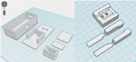
The coating and protection structure of the components, made in a 3D printer, plays an important role in the connection with the serum equipment, allowing the system to be safely and reliably coupled.
This system has the purpose of giving greater security to the health professional, informing if something unexpected happens. Another purpose is to comfort the patient by reducing waiting time for withdrawal of the infusion system.
During the cataract surgery, a special serum is used to maintain the tone of the eye during aspiration of the lens. It is vitally important that the surgical team keep an eye on the amount of available serum, alerting to cases where the serum is ending. If the serum ends during cataract aspiration, the eye may undergo a sudden decompression, with collapse of the anterior chamber and potential intraocular damage. For this reason, this task becomes more of an element of attention to risk during surgery.
Most medical consultations in emergency and first aid institutions carry the administration of intravenous access medication. During this procedure, the patient is rested for a fixed time, accommodated and occupying a space in the environment, which according to the patient's capacity, can generate service queues. One of the variables of comfort of the patient and cost to institution is the time that the same one must remain in the observation / infirmary. In addition to the time involved in the process, the intravenous infusion generates concern of the patient and companions, who continuously monitor their residual volume. There is no agility in the withdrawal or substitution of the medication, there is an increase of anxiety on the part of the patient, and an increase in the time of rotation of the place. In addition, the health team's attention to this level of medication should be reduced.
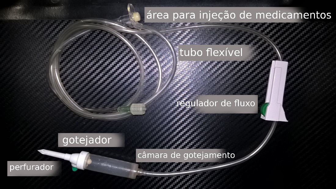
The equipment for serum (Figure 1) includes a set of accessories, consisting of a punch, dripper, drip chamber, drug injection area, flow regulator and flexible tube. It should be used in the infusion of serum, with or without medicines, including the two situations presented.
_
_A serum flow sensor, with visual and audible alerts, should make dependent surgical procedures safer, complementing human attention for the task of warning, and in some cases even being able to replace it.
The automation in the constant conference of the end of medication application, should reduce the total time of stay of the patient in the ward, bringing more comfort and less stress to own and the team, besides reducing the cost of occupying the space for the hospital institution.
The overall goal of the research was to develop, manufacture and test a small, simple, low-cost device that can automate the testing of serum flow by a team. To achieve this goal, secondary goals were defined:
- The design and testing of an infrared light emission system, evaluating signal behavior, measuring reflection, refraction and wave absorption rates, to establish a pattern that indicates the presence or absence of serum within the equipment Invasive.
- The development and testing of a system that uses the results of the previous objective to, using an algorithm, visually and soundly warn the state of the flow in the equipment.
- The creation of a product prototype, resulting from previous analyzes, that is robust and secure, for future implementation and testing.
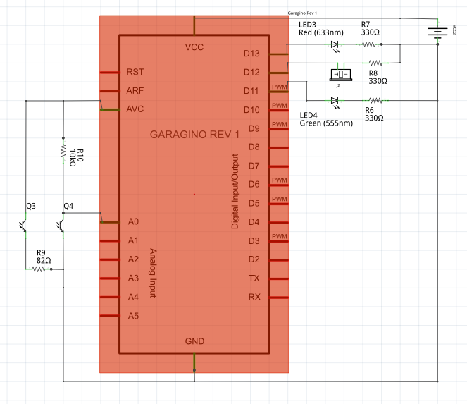
The electronic circuitry consisted of an LTE-302 and LTR-301 optical transceiver and receiver respectively, a micro-controller (Arduino) powered by small LR44 batteries (pulse-shaped battery used in wristwatch), two LEDs Light (LED), a circuit breaker with two positions, various resistors and a buzzer. The prototypes, counted on a structure made in 3D printer.
The dome chamber state sensor was built with an optical emitter and receiver. As an emitter an LTE-302 precision infrared LED was used, and as receiver an LTR-301 precision phototransistor, also sensitive to infrared. When there is a passage of liquid between the transmitter and the receiver, less signal is captured, because the light beam emitted by the LED will have part reflected, refracted or absorbed, on its way to the receiver, creating a partial cut region.
_

Photo 1 - Receiver (LTR-301) and emitter (LTE-302) precision infrared
It is important to note that other types of alternative infrared sensor models, such as the TSOP38238 or GP1A57HRJ00F, were tested at the project design stage and did not achieve the same satisfactory results. The specifications of this sensor model was an important feature. The quality according to the producers did not influence the result, two different brands were tested, to ensure the operation when switching between brands, an adjustment to the values programmed to recognize the state of the equipment was sufficient.
Transistors are components, constructed from semiconductor materials. It has three terminals. When a current is applied at its base, the resistance of the current passing through the internal material between the other terminals is changed. In the case of the infrared photo-transistor, the mechanism is the same, but the resistance is changed depending on the amount of infrared rather than electricity. The resistor divider is a configuration of two resistors connected in series, as shown in figure 2. Since the association is fed by the input voltage (Uentrada), the output voltage (Utilized) refers to the resistor (R below). The expression that allows calculation of Usida is indicated under figure 2. Replacing the resistor Rde below, by the phototransistor LTR-301 we have variable bass, consequently Usage will also vary.
_

Figure 2 - Schematic and theory of the voltage divider
This circuit sensor region delivers a low voltage at the output when the LTR-301 is receiving an intense infrared rate and a high voltage when the LTR-301 is receiving a small infrared rate. The voltage divider circuit gives an output voltage that changes with the amount of infrared.
The Arduino allows the comparison of the electrical voltages delivered to its analog ports every 0.0001 seconds. By connecting the voltage divider output to the analogue port of the Arduino, we can almost automatically and automatically check the voltage as a function of the amount of infrared captured by the LTR-301 phototransistor.
When there is no significant loss of infrared, there is no liquid inside the equipment. When there is a large loss, the device recognizes that there is material between the sensors in the liquid case.
_
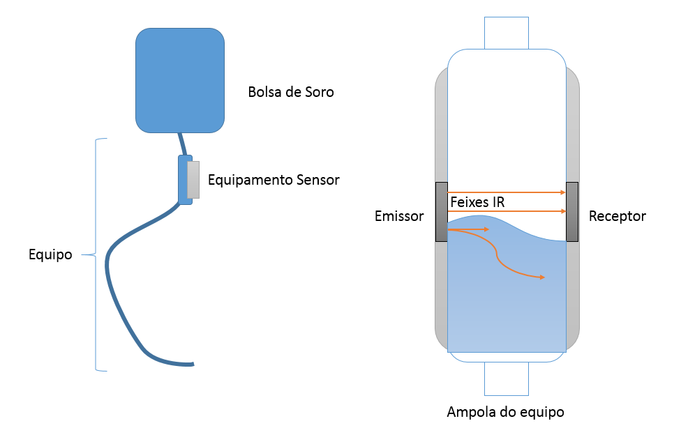
Figure 3 - Explanatory diagram of operation
With the theoretical circuit and sensors designed. Development began in perforated plate for prototyping (Protoboard), where the first tests and stabilization of the operation of the complete theoretical circuit were carried out.
_
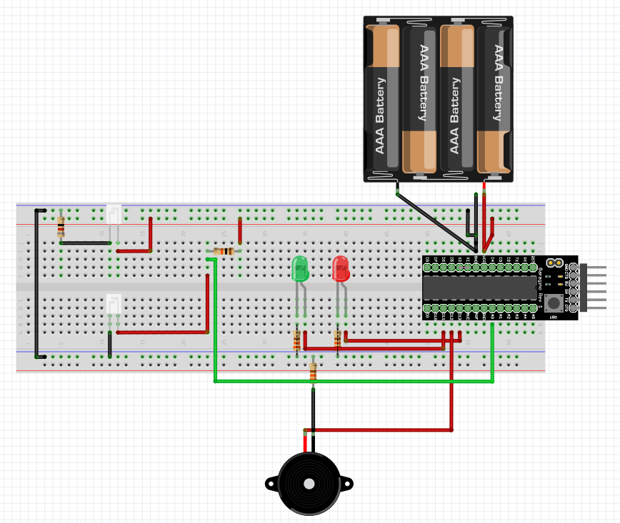
Figure 4 - Electrical scheme assembled in protoboard
Soon after, the first prototypes were assembled, there was a great effort to minimize and compact the size of the device as much as possible.
_
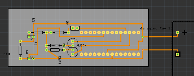
Figure 5 - Making the printed circuit board (PCB)
And
_
_At the beginning of the project some components needed for the construction of the prototype were only found abroad, as is the case with special sensors, which came from the United States. In the course of the research, all materials were located for sale in Brazil. The materials that make up the list required for the construction of the prototype are easily found on the internet or in electronic components store.
| Qty. | Component | Place of purchase | Value |
|---|---|---|---|
| 1 | Micro-controller | http://www.labdegaragem.org/loja/garagino-4/plateas-garagino/garagino-rev1.html | R$ 29,00 |
| 1 | Infrared transmitter and receiver | https://www.robocore.net/modules.php?name=GR_LojaVirtual&prod=288 | RS 7,50 |
| 1 | Resistor of 82 ohm | Electronics Stores | R$ 0,20 |
| 1 | Resistor of 10k ohm | Electronics Stores | R$ 0,20 |
| 3 | Resistors of 330 ohm | Electronics Stores | R$ 0,60 |
| 3 | Batteries LR44 | Electronics Stores | R$ 5,90 |
| 1 | Filament Roller* | http://www.3dmachine.com.br/filamentos/pla/1kg-pla-branco-no-carretel.html | R$ 178,00 |
* Consumption of less than 20g per device
The programming code of the micro-controller has been compact and simple. Initially the communication ports used in the Arduino are configured. In the constant state cycle, the analog port to which the infrared sensor is connected is checked, according to its value the digital ports configured for output are activated according to the logic of alerts.
Void setup () {
  Serial.begin (9600);
  PinMode (13, OUTPUT); // red LED
  PinMode (12, OUTPUT); // Buzzer
  PinMode (11, OUTPUT); // Green LED
}

Void loop () {
  Int sensorIV = analogRead (A0);
  Serial.println (sensorIV);
  If (sensorIV> 990) {// Sensor sensitivity adjustment
    DigitalWrite (11, HIGH);
    DigitalWrite (12, LOW);
    DigitalWrite (13, LOW);
  } Else {
    DigitalWrite (13, HIGH);
    DigitalWrite (12, HIGH);
    DigitalWrite (11, LOW);
  }
  Delay (100);
}During the project, several design models were created to accommodate the electronic circuit, sensors and other parts of the device.
As a battery of tests for the finished prototypes, a kit for serum was mounted on a suitable rod, such that it is mounted in an infirmary, then the device was coupled. An initial stage was defined and configured, where the drip chamber was completely filled with serum. To reach the final state, the equipment was disconnected from the serum bag, then the regulator valve was opened as a result the drip chamber emptied progressively.
In the initial configuration the expected action of the device is the green LED indicative of the present substance light up, the red LED indicates that the absent substance is off and the buzzer changes. In the final configuration the expected action would be the inverse, the green LED indicative of present substance erase, the red LED indicative of absent substance light up and the buzzer alert with an audio.
The process of transition from initial to final state was repeated over supervision for 50 times, comparing the actions performed by the device with the expected actions.
| Number of test | LEDs | Buzzer | Note |
|---|---|---|---|
| 1 | As expected | As expected | |
| 2 | As expected | As expected | Needed repositioning after tremor |
| 3 | As expected | As expected | |
| 4 | As expected | As expected | Needed repositioning after handling |
| 5 | As expected | As expected | |
| 6 | As expected | As expected | Perceived that the device does not read correctly if it is out of the correct position |
The first prototype model finalized and taken to test batteries, was not satisfactory. Made an error of 52% of attempts. Analyzing the data collected in the test, it was concluded that its structure, although light and simple, was not robust enough, several times the clamp used to dock the device, it broke. Any tremor in the infusion system caused the sensors to move, causing a reading error. Easily the sensor was dirty. And the battery ran out in a very short time.
_Figure 7 - First structure model_After each battery of tests is completed, a list of corrections has been written and a new model designed focusing on correcting observed errors.
The project went through numerous versions, until it reached a satisfactory model from a functional point of view. In the battery of fifty tests had 100% of hits.
_Figure 8 - Satisfactory model of functionality aspect. The right clamp for coupling and sensor support. The left, support structure for the rest of the circuit components._After the bench tests, the device was demonstrated '
_Photo(s) 2 - Satisfactory model of functionality aspect. Produced and shared with health professionals._The prototype got a positive return, with lots of praise and some suggestions. The return comments have been filtered, disregarding those that run away from the design aspect, for example, "The device itself should already be embedded in the support rod" - One of the features of the device is portability. The remaining comments were added to the other notes of improvement.
A list of required tasks has been designed, so project tracking is required.
The device battery does not last long enough. With the battery system based on LR44 or even on CR2032, more powerful, it was not possible to follow a common process of whole infusion. A new feed system needs to be planned and tested.
The structure of the device is too large, it needs to be compacted. In order to achieve a robust model that would withstand accidental drops and not lose the position of the sensors according to the tremors in the device, it was necessary to widen the sides and increase the size, consequently causing loss of ergonomics in the handling and affecting the aesthetics of the device.
It was not possible to perform tests in a practical environment, where the device would be used in everyday life. It is necessary to test the system in practice, in environments such as wards, with volunteers who can express opinions and suggestions for improvement. By increasing the tests, situations are amplified and new problems can be detected.
By optimizing the device, it would be interesting to study a way to share the project with communities that can collaborate for improvements or new ideas
Based on the necessary tasks, we suggest a new complementary schedule.
| Activities | Occurrence | ||||||||||||
|---|---|---|---|---|---|---|---|---|---|---|---|---|---|
| Ano | 2016 | 2017 | |||||||||||
| Month | 7 | 8 | 9 | 10 | 11 | 12 | 1 | 2 | 3 | 4 | 5 | 6 | 7 |
| Beginning of the new stages of the project. | ✓ | ||||||||||||
| Study on efficient and compact feeding systems for Arduino projects. | ✓ | ✓ | |||||||||||
| Analysis and implementation of the possibilities discovered about the feeding system. | ✓ | ✓ | |||||||||||
| Study on ergonomics and structure. | ✓ | ✓ | |||||||||||
| Analyze and implementthe possibilities discovered about ergonomics and structure. | ✓ | ✓ | |||||||||||
| Study on copyright and project sharing. | ✓ | ✓ | |||||||||||
| Analyze and implement the possibilities discovered about project sharing. | ✓ | ✓ | |||||||||||
| Study on ergonomics and structure. | ✓ | ✓ | ✓ | ||||||||||
| Writing and preparation of handwritten documentation. | ✓ | ✓ | ✓ | ✓ | |||||||||
| Student performance and project progress report. | ✓ | ✓ | |||||||||||
| Job summary typing for congress. | ✓ | ||||||||||||
| Scientific congress. | ✓ | ||||||||||||
| Submission of Final Report. | ✓ | ||||||||||||
It is not possible to estimate the costs for the battery system, since a more in-depth study should be carried out for an efficient and low-cost solution.
There will be no additional cost for studies related to ergonomics, since the materials already acquired in the first stage of the study will be used.
The project is the initiative of the researcher, so it will not receive external funding. As a resource provider, we will have the Ocular Bioengineering Laboratory, which already has adequate funding for this type of activity.
This Project is part of the projects linked to the project "Idealization, Prototyping and Testing of Ophthalmic Microplates". Approved under number 0091/11
The Physiological Serum check system used correctly can present excellent results in the area of Health, in order to avoid complications guaranteed safety, bring comfort to the user and reducing costs of the process for professionals, patients and institutions.
The circuit will enable many implementations with easy handling and without the need for many instructions allowing the user layers have a great adaptation and acceptability.
Based on the user comments and results obtained in the tests carried out in the first phase of the study. It is expected to raise the quality of the device so that the prototype approaches an end product.
- Maeda Sayuri Tanaka, Campedelli Maria Coeli. Escalpe e equipo de soro: opinião de enfermeiras quanto aos requisitos essenciais de qualidade. Rev. bras. enferm. [Internet]. Setembro 1991; 44( 2-3 ): 124-135. Disponível em: http://www.scielo.br/scielo.php?script=sci_arttext&pid=S0034-71671991000200017&lng=en. http://dx.doi.org/10.1590/S0034-71671991000200017.
- LITE-ON Eletronics. LTR-301 Data Sheet [PDF]. https://www.sparkfun.com/datasheets/Components/LTR-301.pdf
- LITE-ON Eletronics. LTE-302 Data Sheet [PDF]. https://www.sparkfun.com/datasheets/Components/LTE-302.pdf
- Michael N. Wiggins. Balanced salt solution alarm [Internet]. US 20080204261 A1. 2008 Ago 28. Acesso em: 2015 Mai 01. Endereço eletrônico com a expressão Disponível em: http://www.google.com/patents/US20080204261
- James W. Bennett, Leonid F. Matsiev. Intravenous fluid monitoring [Internet]. US 8728025 B2. 2014 Mai 20. Acesso em: 2016 Mai 01. Endereço eletrônico com a expressão Disponível em: http://www.google.com.br/patents/US8728025
- https://www.arduino.cc/en/Reference/AnalogRead
- https://www.arduino.cc/en/Tutorial/AnalogInput
- www.ceee.com.br/pportal/ceee/Component/Controller.aspx?CC=3330
