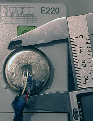
A simple Arduino project for optical readout of Landis+Gyr E220 power meters. Requires an ESP8266 board such as the Wemos D1 Mini or SP-Cow ESP8266, an ~880nm infrared phototransistor like BPW96C, some wiring and some 20 to 680 ohm resistor, and for example a door ring magnet ca. 33mm outer diameter with an 5mm (M5) inner hole through with to glue/epoxy the 5mm diameter phototransistor.
The E220 meter must be switched once into Extended INFO mode via its user menu (E220 user guide section 5.4.1). This requires entry of a 4-digit PIN that has to be requested from the utility or metering service company.
Brute forcing the PIN is doable (not implemented here). The meter does not lock on incorrect attempts. Time perhaps ~20 sec/cycle * all 10000 combinations = ~56 hours max.
Once extended info is enabled, the E220 screen continually displays the live power draw from / feed into the grid, and the infrared interface sends the same info as an SML formatted data frame. One frame per second.
The infrared interface is unidirectional serial with 9600,8,N,1 and probably adheres to DIN EN 62056-21 "D0" interface specs.
The E220 is a very budget model with a very limited set of metering fields. Out of the IEC 62056 OBIS codes it reports only two:
- 1.8.0 = positive active energy as a total since meter installation
- 16.7.0 = sum active instantaneous power 'A+ - A-'
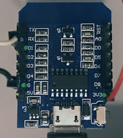
Example with SP-Cow ESP8266 Amazon B093G72SHN. The IR phototransistor BPW96C needs its emitter pin (round side) tied to GND. The collector pin (flattened side) to ESP8266 board pin D1. The same D1 pin needs a 20..680 ohm resistor for pull-up to Vcc/3.3V.
Need the Arduino IDE, adding ESP8266 into the board manager (c.f. instructions). The board used here is the Wemos D1 Mini. Under the Arduino menu Tools, Board, it is called "Lolin(Wemos) D1 Mini (Clone)". Config is CPU 80 MHz and 4MB.
The Arduino sketch is under ./d0mqtt/
From the code Library need: ESP8266WiFi, SoftwareSerial, PubSubClient, WiFiUdp, ESP8266WebServer.
Before uploading the sketch, adjust the hard coded entries:
const char ssid[] = "<your wlan ssid>";
const char pass[] = "<your wlan passwd>";
const char MQTT_HOST[] = "<ip of mqtt host like 192.168.0.100>";
const int  MQTT_PORT = 1883;
#define SML_UDP_DEST_PORT      3220    // send undecoded SML payload to this port of MQTT Host
#define PRICE_CENT_PER_KWH     37      // Main tariff e.g. €0,31/kWh + 19% tax
#define TARIFF_START_SINCE_KWH  0      // Starting from which kWh reading the above price tariff applies
The ESP sends topics 'e220/P_W' and 'e220/E_Wh'. Example trace:
pi@raspberrypi:~$ mosquitto_sub -t "e220/#" -v
e220/P_W 272
e220/E_Wh 71611.5
e220/P_W 231
e220/E_Wh 71611.5
...
To get MQTT data via Telegraf into InfluxDB (and then e.g. Grafana), there is an example config under ./telegraf-conf/
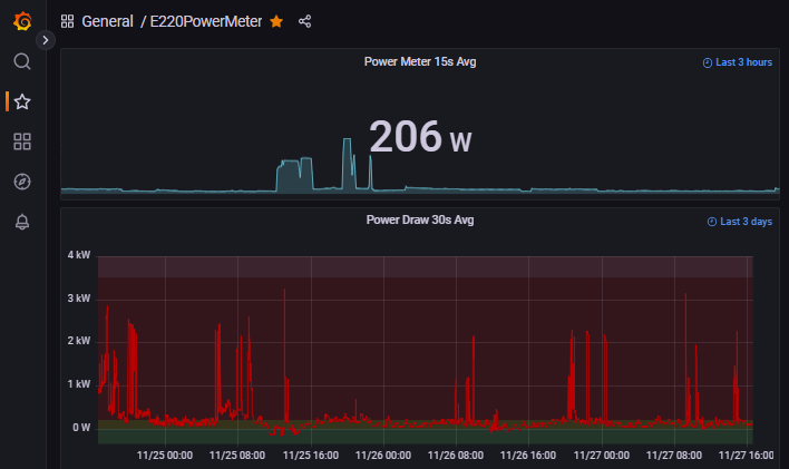
The example Grafana JSON file under ./grafana-conf/ provides a very simple dashboard like:

A copy of SML frame payload is sent as an UDP packet to the MQTT host but a different port than the MQTT port. The UDP can be captured (e.g., ./debugCapture/pyUDPrx.py) and decoded through libsml (e.g., ./debugCapture/decodeE220sml.c).
Example:
pi@raspberrypi:~/e220_esp8266/debugCapture/ $ sudo aptitude install libsml-dev libsml1
pi@raspberrypi:~/e220_esp8266/debugCapture/ $ make
pi@raspberrypi:~/e220_esp8266/debugCapture/ $ make capture
From ('192.168.0.179', 53047) received 226 bytes : 76050083cb0962006200...
SML file (3 SML messages, 227 bytes)
SML message  101
SML message  701
SML message  201
OBIS data
1-0:96.50.1*1#LGZ#
1-0:96.1.0*255#0a 01 xx xx xx xx xx xx xx xx #
1-0:1.8.0*255#237431.6#Wh
1-0:16.7.0*255#108#W
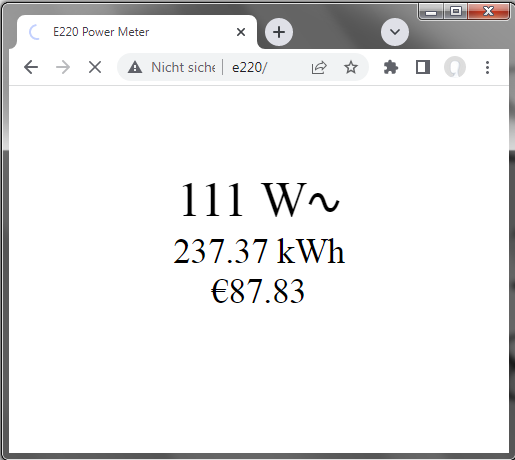
The ESP also serves a very simple status page. It refreshes every 5 seconds. Example page: 
SoftwareSerial is used for optical serial reception (pin D1) since ESP8266 has only one hardware serial port and that is already occupied by the Arduino USB-Serial program upload and serial monitor interface.
The serial monitor interface outputs a copy of live meter readings, and raw SML frame debug data if enabled.

