-
Notifications
You must be signed in to change notification settings - Fork 37
Wireframe using a Geometry Shader
Wireframe drawing is one of the basic representations of a model in 3D graphics. It allows to explicitly visualise model complexity - the number, shape and density of polygons are made much more obvious than when drawing an opaque model.
OpenGL can be switched to draw all polygons as wireframe using the glPolygonMode function. However, in OpenGL4, this mode doesn't provide any means of controlling the style of the drawing, the width of the line (for example, glLineWidth parameter is limited to 1.0 in most modern implementations of the OpenGL standard).
A flexible way to convert one type of primitive to another (and for primitive manipulation in general), is to use a Geometry Shader. This tutorial shows how to use a geometry shader to display a polygonal mesh as wireframe, and to manipulate its line properties.
As the starting point, we will use the simple setup from the opengl toolbar of Possumwood. This should bring in a teapot model, with a vertex and fragment shader set up, displaying the model with normals explicitly loaded from a file:
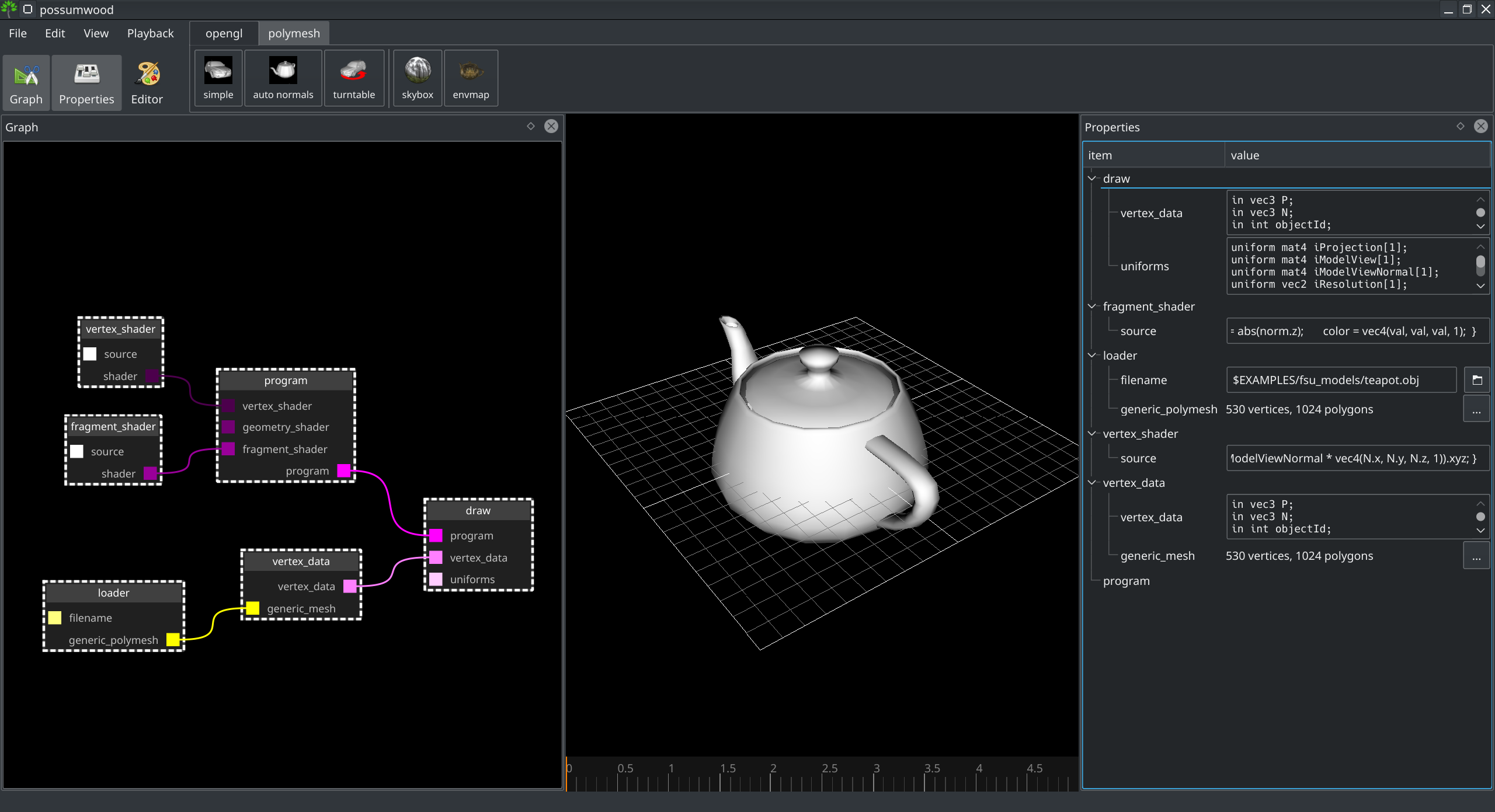
This setup does not include a geometry shader yet - if not present, OpenGL will just transparently pass the data from the vertex shader into rasterization.
As the first step, we need to add the geometry shader to our setup. Unfortunately, just creating a render/geometry_shader node and connecting it to the right input of the render/draw node is not enough in this case - the shader compilation will error with missing normal fragment shader input:
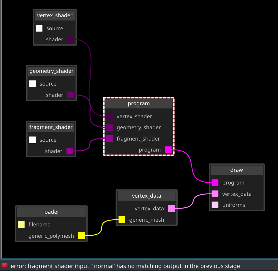
The normal value was originally created by the vertex shader and passed into the fragment shader. The default code of the geometry shader does not take that into account. We need to change it so its inputs (represented as arrays) are passed to its outputs (represented using a function-based interface):
#version 150

layout(triangles) in;
layout(triangle_strip, max_vertices = 3) out;

in vec3 normal[];
out vec3 vertexNormal;

void main() {
	for(int i = 0; i < 3; i++) {
		gl_Position = gl_in[i].gl_Position;
		vertexNormal = normal[i];
		EmitVertex();
	}
	EndPrimitive();
}
Because the fragment input is now called vertexNormal, we need to adjust the fragment shader accordingly:
#version 130

out vec4 color;

in vec3 vertexNormal;

void main() {
	vec3 norm = normalize(vertexNormal);

	float val = abs(norm.z);
	color = vec4(val, val, val, 1);
}
Which leads to the same output we've seen before adding the geometry shader:
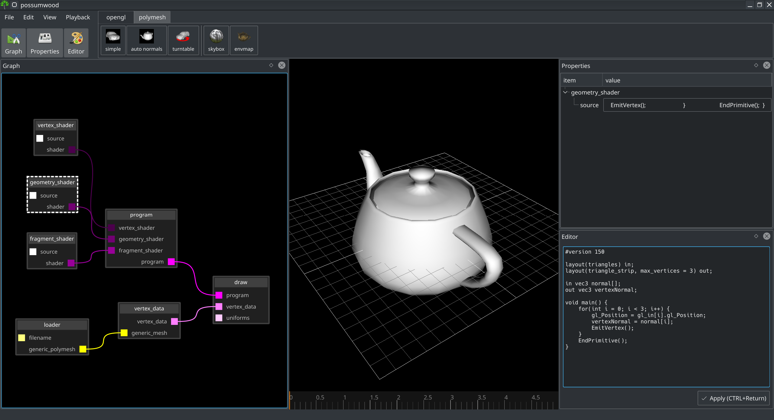
Geometry shaders allow to easily convert from one type of primitive to another, by simply changing the layout type. To convert polygons to lines, we can just change the layout to line_strip and pass through the original vertices. To make sure we represent the whole triangle, we need to pass one vertex twice - that will be the beginning and the end of a strip, forming a closed loop.
#version 150

layout(triangles) in;
layout(line_strip, max_vertices = 4) out;

in vec3 normal[];
out vec3 vertexNormal;

void main() {
	for(int i = 0; i < 4; i++) {
		gl_Position = gl_in[i % 3].gl_Position;
		vertexNormal = normal[i % 3];
		EmitVertex();
	}
	EndPrimitive();
}
This leads to a simple wireframe, similar to what we would achieve by switching the glPolygonMode:

If we want to have more control over the style of line drawing (e.g., line thickness), we need to be able to create camera-facing polygons to represent these thick lines. For this, we need access to camera transformation, and it might be just easier if all view-related transformations are computed inside the geometry shader instead of the vertex shader.
To implement this, our vertex shader becomes trivial, just passing the input data along:
#version 130

out vec3 norm;

in vec3 P;
in vec3 N;

void main() {
	norm = N;
   	gl_Position = vec4(P, 1);
}
Most of its complexity is passed to the geometry shader:
#version 150

uniform mat4 iProjection;
uniform mat4 iModelView;
uniform mat4 iModelViewNormal;

layout(triangles) in;
layout(triangle_strip, max_vertices = 3) out;

in vec3 norm[];

out vec3 vertexNormal;

void main() {
	for(int i = 0; i < gl_in.length(); i++) {
		vertexNormal = (iModelViewNormal * vec4(norm[i], 0)).xyz;;
		gl_Position = iProjection * iModelView * gl_in[i].gl_Position;
		EmitVertex();
	}
	EndPrimitive();
}
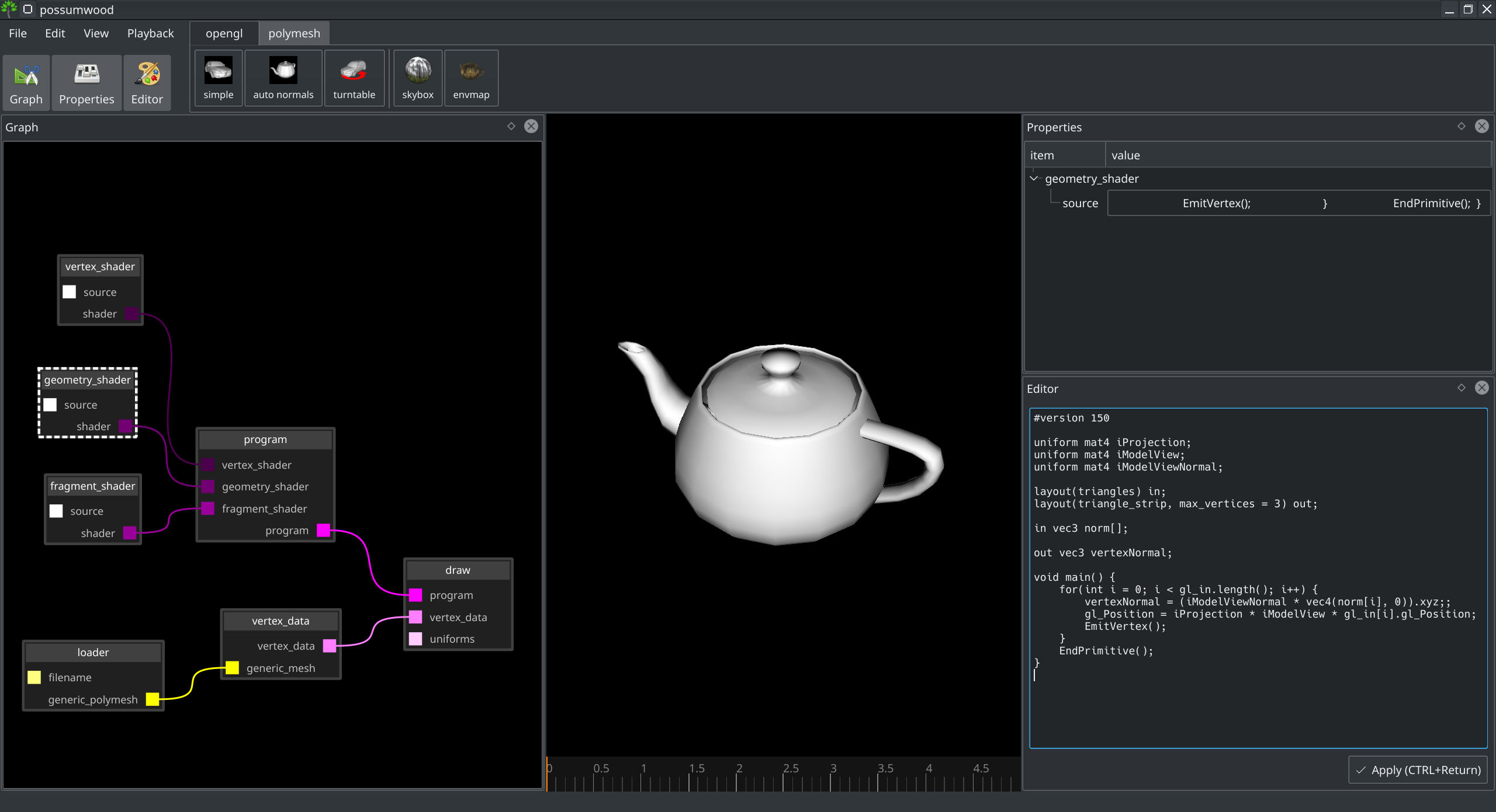
This leads to the same result as above, achieved in a different way:
To simplify the code, can wrap away the necessary transformations into a separate function:
#version 150

uniform mat4 iProjection;
uniform mat4 iModelView;
uniform mat4 iModelViewNormal;

layout(triangles) in;
layout(triangle_strip, max_vertices = 4) out;

in vec3 norm[];

out vec3 vertexNormal;

void doEmitVertex(vec3 p, vec3 n) {
	vertexNormal = (iModelViewNormal * vec4(n, 0)).xyz;;
	gl_Position = iProjection * iModelView * vec4(p, 1);
	EmitVertex();
}

void main() {
	for(int i = 0; i < gl_in.length(); i++) {
		doEmitVertex(
			gl_in[i].gl_Position.xyz,
			norm[i]
		);
	}
	EndPrimitive();
}
As a preparation for emitting strips of polygons to represent lines, let's first switch back to a line strip, and wrap-away emitting individual line segments:
#version 150

uniform mat4 iProjection;
uniform mat4 iModelView;
uniform mat4 iModelViewNormal;

layout(triangles) in;
layout(line_strip, max_vertices = 12) out;

in vec3 norm[];

out vec3 vertexNormal;

void doEmitVertex(vec3 p, vec3 n) {
	vertexNormal = (iModelViewNormal * vec4(n, 0)).xyz;

	// camera space position
	vec4 pos = iProjection * iModelView * vec4(p, 1);

	gl_Position = pos;
	EmitVertex();
}

void doEmitLine(vec3 p1, vec3 n1, vec3 p2, vec3 n2) {
	doEmitVertex(p1, n1);
	doEmitVertex(p2, n2);
}

void main() {
	for(int i = 0; i < gl_in.length(); i++) {
		doEmitLine(
			gl_in[i].gl_Position.xyz,
			norm[i],
			gl_in[(i+1) % gl_in.length()].gl_Position.xyz,
			norm[(i+1) % gl_in.length()]
		);
	}
	EndPrimitive();
}
In this version, the vec4 pos variable is in camera space (or clip space), implementing perspective projection. The additional w attribute is part of a vector representation in homogeneous coordinates, necessary to represent perspective projection and generic affine transformations.
To translate the pos variable back to a simple 3D coordinate space, we can simply divide the 3D part of the vector by its w component:
pos = pos / pos.w;
This maps the x, y, and z values to interval [-1..1] (i.e., clip coordinates), which makes them easier to manipulate. However, inserting this operation into the shader has no impact on the output (OpenGL performs this normalisation internally as well).
The view (or clip) space is essentially 2-dimensional - its x and y coordinates correspond to position of each vertex on the screen, while its z coordinate is only used to decide visibility via the z-buffer algorithm. The task of making the lines thicker then becomes a simple 2D problem - for each line, we emit two triangles, with vertices computed by the direction vector and a 2D vector perpendicular to the direction:
vec2 edge = (p2-p1).xy;
edge = normalize(vec2(edge.y, -edge.x));
This leads to a geometry shader where each of the two points of each line is emitted as two vertices, forming a 2-triangle strip for each line:
#version 150

uniform mat4 iProjection;
uniform mat4 iModelView;
uniform mat4 iModelViewNormal;

layout(triangles) in;
layout(triangle_strip, max_vertices = 12) out;

in vec3 norm[];

out vec3 vertexNormal;

float LINE_WIDTH = 0.01;

void doEmitVertex(vec4 p, vec3 n, vec2 edge) {
	// a common normal
	vertexNormal = (iModelViewNormal * vec4(n, 0)).xyz;

	// edges of the line, emitted as 2 vertices
	gl_Position = p + vec4(edge, 0, 0);
	EmitVertex();
	gl_Position = p - vec4(edge, 0, 0);
	EmitVertex();
}

void doEmitLine(vec3 p1, vec3 n1, vec3 p2, vec3 n2) {
	// normalize p1
	vec4 np1 = iProjection * iModelView * vec4(p1, 1);
	np1 = np1 / np1.w;

	// normalize p2
	vec4 np2 = iProjection * iModelView * vec4(p2, 1);
	np2 = np2 / np2.w;

	// perpendicular "edge" vector
	vec2 edge = (np2-np1).xy;
	edge = normalize(vec2(edge.y, -edge.x)) * LINE_WIDTH;

	// emit the line vertices
	doEmitVertex(np1, n1, edge);
	doEmitVertex(np2, n2, edge);
}

void main() {
	for(int i = 0; i < gl_in.length(); i++) {
		// each "line" is emitted as a triangle strip
		doEmitLine(
			gl_in[i].gl_Position.xyz,
			norm[i],
			gl_in[(i+1) % gl_in.length()].gl_Position.xyz,
			norm[(i+1) % gl_in.length()]
		);

		EndPrimitive();
	}
}
Voilà, we have a render with thick lines!
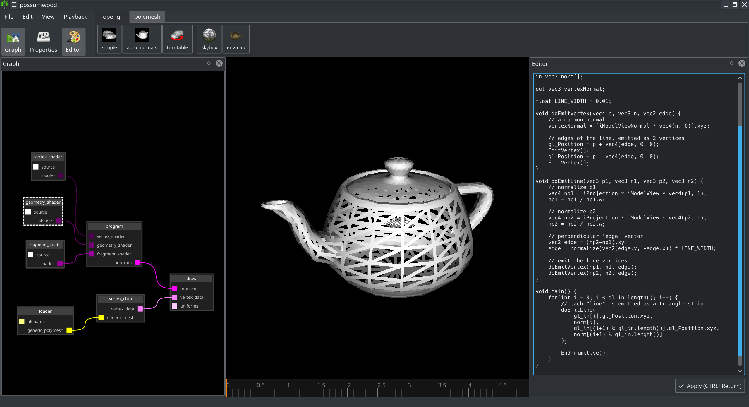
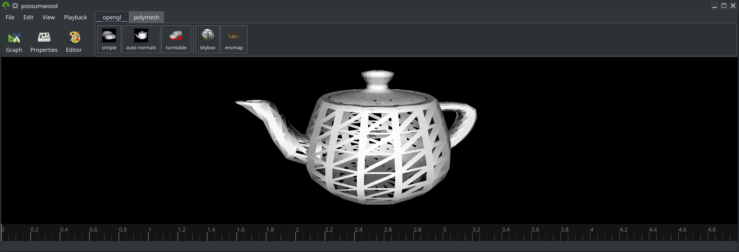
The line width parameter is defined in fraction of the screen space, which brings an interesting issue - the line width is relative to the screen size, and not consistent when the window is resized:
Modifying the previous code to allow specifying line width in pixels requires the knowledge of screen resolution. Fortunately the viewport uniform source (and the default set of uniforms) provide this in a vec2 iResolution uniform variable:
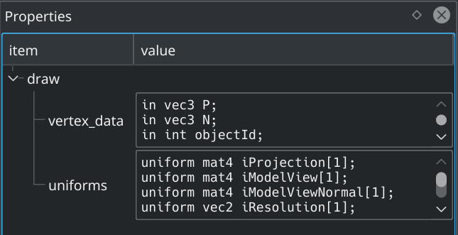
This allows us to adjust the edge vector to produce always the same pixel-width:
#version 150

uniform mat4 iProjection;
uniform mat4 iModelView;
uniform mat4 iModelViewNormal;
uniform vec2 iResolution;

layout(triangles) in;
layout(triangle_strip, max_vertices = 12) out;

in vec3 norm[];

out vec3 vertexNormal;

float LINE_WIDTH = 10; // now in pixels, resolution independent!

void doEmitVertex(vec4 p, vec3 n, vec2 edge) {
	// a common normal
	vertexNormal = (iModelViewNormal * vec4(n, 0)).xyz;

	// edges of the line, emitted as 2 vertices
	gl_Position = p + vec4(edge, 0, 0);
	EmitVertex();
	gl_Position = p - vec4(edge, 0, 0);
	EmitVertex();
}

void doEmitLine(vec3 p1, vec3 n1, vec3 p2, vec3 n2) {
	// normalize p1
	vec4 np1 = iProjection * iModelView * vec4(p1, 1);
	np1 = np1 / np1.w;

	// normalize p2
	vec4 np2 = iProjection * iModelView * vec4(p2, 1);
	np2 = np2 / np2.w;

	// perpendicular "edge" vector
	vec2 edge = (np2-np1).xy;
	edge = normalize(vec2(edge.y, -edge.x));

	// adjust for screen resolution
	edge.x = edge.x / iResolution.x * LINE_WIDTH / 2.0;
	edge.y = edge.y / iResolution.y * LINE_WIDTH / 2.0;

	// emit the line vertices
	doEmitVertex(np1, n1, edge);
	doEmitVertex(np2, n2, edge);
}

void main() {
	for(int i = 0; i < gl_in.length(); i++) {
		// each "line" is emitted as a triangle strip
		doEmitLine(
			gl_in[i].gl_Position.xyz,
			norm[i],
			gl_in[(i+1) % gl_in.length()].gl_Position.xyz,
			norm[(i+1) % gl_in.length()]
		);

		EndPrimitive();
	}
}
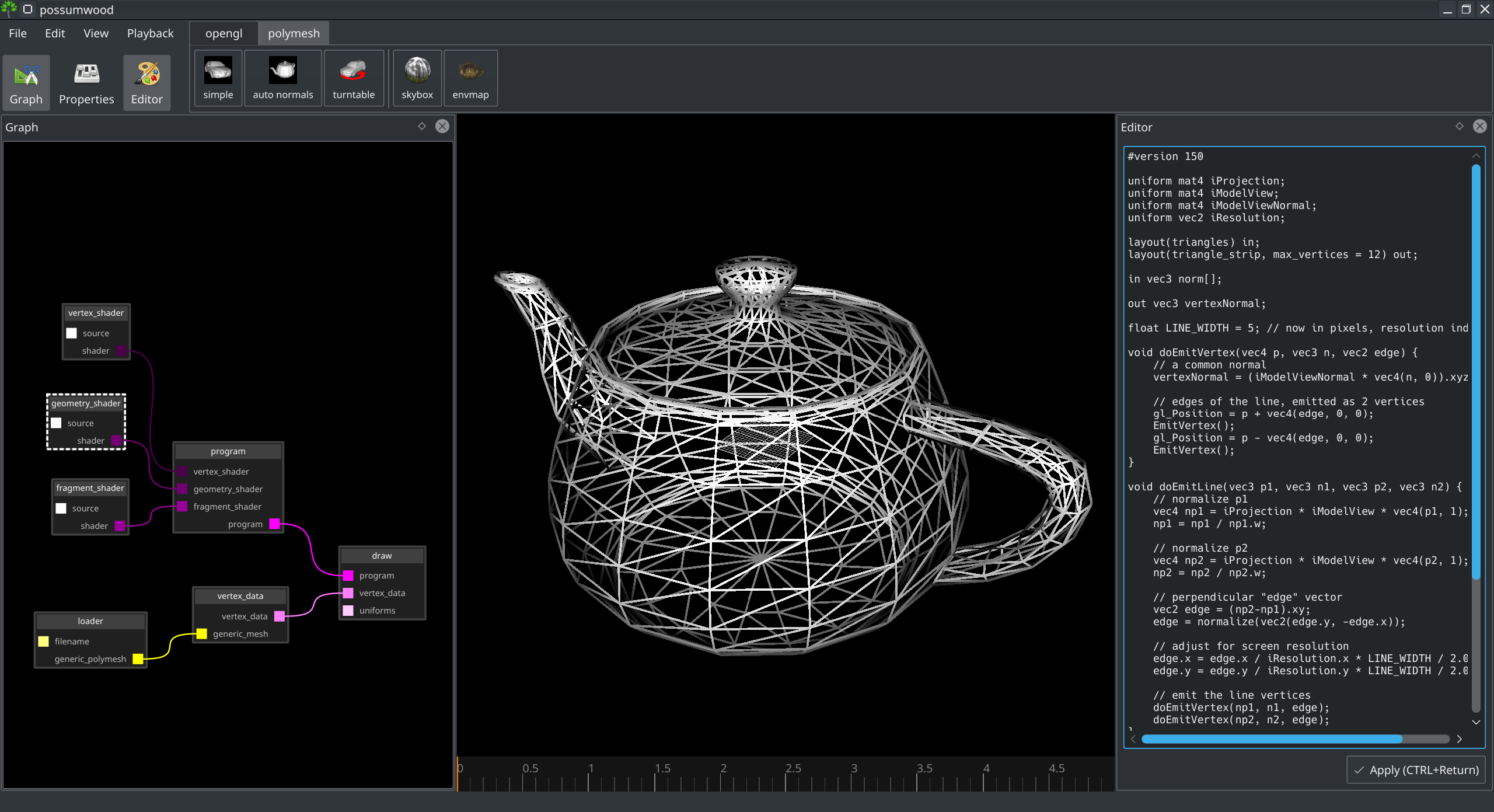
This leads to the final result of this tutorial, a wireframe display with thick lines, rendered using polygons emitted from a geometry shader:
Possumwood is an open source project - please contribute!