| Pin | Symbol | Description |
|---|---|---|
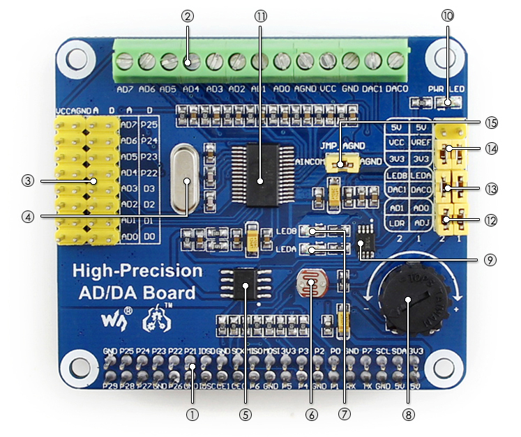
| 1, 17 | 3.3V | Power supply (3.3V) |
| 2 | 5V | Power supply (5V) |
| 3, 5, 7, 8, 10, 18, 22, 24, 26, 27, 28, 29, 32, 36, 38, 40 | NC | NC |
| 6, 9, 14, 20, 25, 30, 34, 39 | GND | Ground |
| 11 | DRDY | ADS1256 data ready output, low active |
| 12 | RESET | ADS1256 reset input |
| 13 | PWDN | ADS1256 sync/power off input, low active |
| 15 | CS0 | ADS1256 chip select, low active |
| 16 | CS1 | DAC8532 chip select, low active |
| 19 | DIN | SPI data input |
| 21 | DOUT | SPI data output |
| 23 | SCK | SPI clock |
| 31 | GPIO | extend to sensor interface |
| Connector | Pin number | Pin name | Signal name | STM32 pin | Function |
|---|---|---|---|---|---|
| CN2 | 1 | NC | - | - | - |
| 2 | IOREF | - | - | 3.3 V reference | |
| 3 | NRST | STM_NRST | NRST | Reset | |
| 4 | 3.3 V | - | - | 3.3 V input/output | |
| 5 | 5V | - | - | 5V | |
| 6 | GND | - | - | GND | |
| 7 | GND | - | - | GND | |
| 8 | VIN | - | - | Power input | |
| CN4 | 1 | A0 | ARD.A0-ADC | PC5 | ADC |
| 2 | A1 | ARD.A1-ADC | PC4 | ADC | |
| 3 | A2 | ARD.A2-ADC | PC3 | ADC | |
| 4 | A3 | ARD.A3-ADC | |||
| 5 | A4 | ARD.A4-ADC | PC1 | ADC / I2C3_SDA | |
| 6 | A5 | ARD.A5-ADC | PC0 | ADC / I2C3_SCL | |
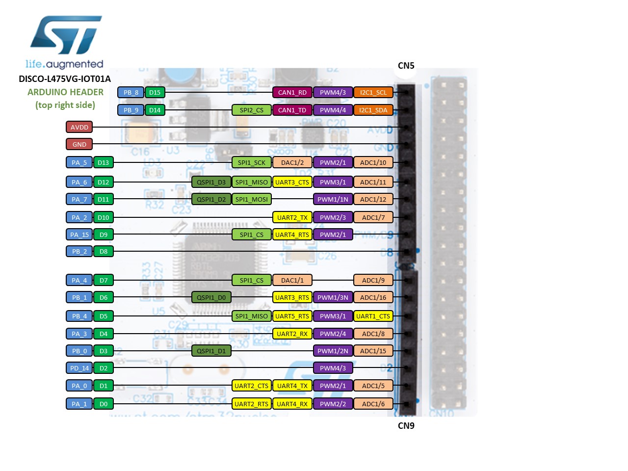
| CN1 | 10 | SCL/D15 | ARD.D15-I2C1_SCL | PB8 | I2C1_SCL |
| 9 | SDA/D14 | ARD.D14-I2C1_SDA | PB9 | I2C1_SDA | |
| 8 | AVDD | VDDA | - | VDDA | |
| 7 | GND | GND | - | Ground | |
| 6 | SCK/D13 | ARD.D13- SPI1_SCK/LED1 | PA5 | SPI1_SCK / LED1 | |
| 5 | MISO/D12 | ARD.D12-SPI1_MISO | PA6 | SPI1_MISO | |
| 4 | PWM/MOSI/D 11 | ARD.D11- SPI1_MISO/PWM | PA7 | SPI1_MOSI /TIMxx | |
| 3 | PWM/CS/D10 | ARD.D10- SPI_SSN/PWM | PA2 | TIM2_CH3 | |
| 2 | PWM/D9 | ARD.D9-PWM | PA15 | TIM2_CH1 | |
| 1 | D8 | ARD.D8 | PB2 | GPIO | |
| CN3 | 8 | D7 | ARD.D7 | PA4 | GPIO |
| 7 | PWM/D6 | ARD.D6-PWM | PB1 | TIM3_CH4 | |
| 6 | PWM/D5 | ARD.D5-PWM | PB4 | TIM3_CH1 | |
| 5 | D4 | ARD.D4 | PA3 | TIMxx | |
| 4 | PWM/D3 | ARD.D3- PWM/INT1_EXTI0 | PB0 | TIM3_CH3 / EXTI0 | |
| 3 | D2 | ARD.D2-INT0_EXTI14 | PD14 | EXTI14 | |
| 2 | TX/D1 | ARD.D1-UART4_TX | PA0 | UART4_TX | |
| 1 | RX/D0 | ARD.D0-UART4_RX | PA1 | UART4_RX |
ADC Library : ADS1256 DAC Library : DAC8532
-
Connect a USB cable between the USB port on the board and the host computer.
-
Run the following command to build the example project and program the microcontroller flash memory:
- Mbed CLI 2
$ mbed-tools compile -m <TARGET> -t <TOOLCHAIN> --flash
- Mbed CLI 1
$ mbed compile -m <TARGET> -t <TOOLCHAIN> --flash
Your PC may take a few minutes to compile your code.
Alternatively, you can manually copy the binary to the board, which you mount on the host computer over USB.

