| NOTE: |
|---|
| SimHID G1000 was designed to apply five ALPS EC11EBB24C03 as the dual shaft rotary encoder, however this product is discontinued now. Fortunately, BOURNS PEC11D-4120F-S0015 can be installed instead of EC11EBB24C03. This is fully compatible with ALPS product except shaft geometry. If you install BOURNS PEC11D-4120F-S0015, print another design for dual shaft knobs. |
The operable parts of SimHID G1000, the rotary encoders and push buttons, are distributed and mounted on three PCBs.
The right board is the main board. The MCU STM32F411CCU which is installed on the right board exports USB full speed PHY and communicate with PC via it.
That MCU also observes all operable components state via 16bits SPI I/O expanders, MCP23S18-E/MJ, on each PCB.
Each PCB is connected with each other via 8-wire interconnect that consists 2 for power supply, 3 for SPI, and 3 for chip select.
I designed two variants of the PCB using Autodesk Eagle and same functions embedded in Autodesk Fusion 360. In the first variant, designed in March 2021, I used the MCP23S18-E/MJ (QFN24) as the I/O expander. However, this component never made it to JLCPCB’s parts library. At the time, with the chip shortage in full swing, other components were also out of stock, so I didn’t pay much attention to it. Now that the supply-demand situation for chips has improved, I decided to design a variant that uses components easier to manufacture with JLCPCB’s PCBA service. In the second variant, designed in September 2023, I replaced the MCP23S18-E/MJ with the MCP23S17-E/ML (QFN28) and reduced the components mounted on the back of the PCB to only the Micro USB connector.
The design files of each PCB and the files required for manufacturing such as gerber files can be found below.
| PCB Variant | Eagle design files | Gerber files | Files for JLCPCB PCB assembly service |
|---|---|---|---|
| Variant 1 | handsoldering/individuals | PCB.zip | assembly.zip |
| Variant 2 | reflow/individuals | PCB_var2.zip | assembly_var2.zip |
The above both archive files, PCB*.zip and assembly*.zip, are compliant with the rule of JLCPCB.
You can submit these archive files to JLCPCB PCB assembly service as it is.
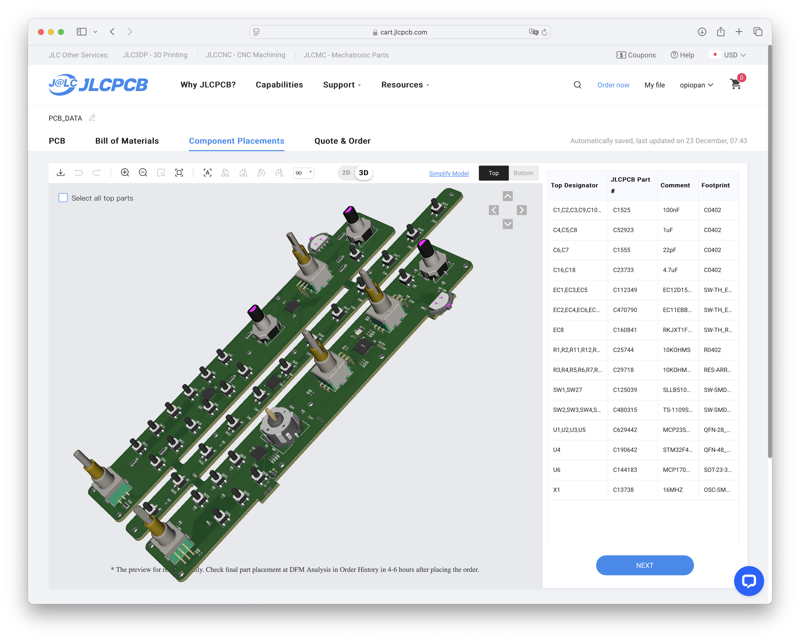
When using the above file to manufacture the PCB at JLCPCB, specify the following parameters during production.
| Parameter | Specification |
|---|---|
| Different Design | 3 |
| PCB Thickness | 1.0 mm |
| Tooling holes | Added by Customer |
| PCBA Type / Assembly Side |
My recommendation is 'Economic' for the 'PCBA Type' and 'Top Side' for the 'Assembly Side'. When assembling components on both sides of the board, you must select 'Standard' for the 'PCBA Type'. This results in a significant cost increase. For example, if you manufacture two units of Variant 2, selecting 'Economic' and 'Top Side' costs $188.07, whereas selecting 'Standard' and 'Both Side' increases the price to $270.25. That’s quite a large amount to pay for soldering just two Micro USB connectors, each costing only $0.34, isn’t it? If you use the PCBA service to assemble only the top side of Variant 1, you’ll need to manually solder the MCP1703AT-3302E/CB and ZX62-B-5PA(33) on the bottom side yourself. For Variant 2, you only need to solder the ZX62-B-5PA(33). |
| Components | Value / Product Number | Remarks |
|---|---|---|
| U1, U2, U3, U5 | MCP23S18-E/MJ or MCP23S17-E/ML | 16bits SPI I/O expander |
| U4 | STM32F411CCU | |
| U6 | MCP1703AT-3302E/CB | SOT-23 LDO |
| J1 | ZX62-B-5PA(33) | Hirose Micro USB receptacle connector |
| J6 | MOLEX 53047-0410 | OPTIONAL for debugging Firmware downloading can be proceeded by using DFU mode instead debugger |
| X1 | 16MHz Crystal (3225) | load capacitance: 10pF |
| C1, C2, C3, C9, C10, C11, C12, C13, C14, C15, C17, C19, C20 | 0.1uF (0402) | |
| C4, C5, C8 | 1uF (0402) | |
| C6, C7 | 22pF (0402) | need to change value if X1's load capacitance is not 10pF |
| C16, C18 | 4.7uF (0402) | |
| R1, R2, R11, R12, R13, R14, R15, R16, R17, R18, R19, R20, R21, R22, R23, R24, R25, R26, R27, R28, R29, R30, R31, R32, R33, R34, R35, R36, R37, R38, R39, R40, R41, R42, R43, R44, R45, R46, R47, R48, R49, R50, R51, R52, R53, R54, R55, R56, R57, R58, R59 |
10k ohm (0402) | |
| R3, R4, R5, R6, R7, R8, R9, R10 | 10k ohm x 4 (0603 x 4) | |
| SW1, SW27 | SLLB510100 | |
| SW2, SW3, SW4, SW5, SW6, SW7, SW8, SW9, SW10, SW11, SW12, SW13, SW14, SW15, SW16, SW17, SW18, SW19, SW20, SW21, SW22, SW23, SW24, SW25, SW26, SW28, SW29, SW30, SW31, SW32, SW33, SW34 |
4.5mm x 4.5mm tact switch | 4.3mm height |
| EC1, EC3, EC5 | EC12D1524403 | 1 axis rotary encoder with push button |
| EC2, EC4, EC6, EC7, EC9 | EC11EBB24C03 or PEC11D-4120F-S0015 | 2 axes rotary encoder with push button |
| EC8 | RKJXT1F42001 | 4 directional joystick with 1 axis rotary encoder and push button |
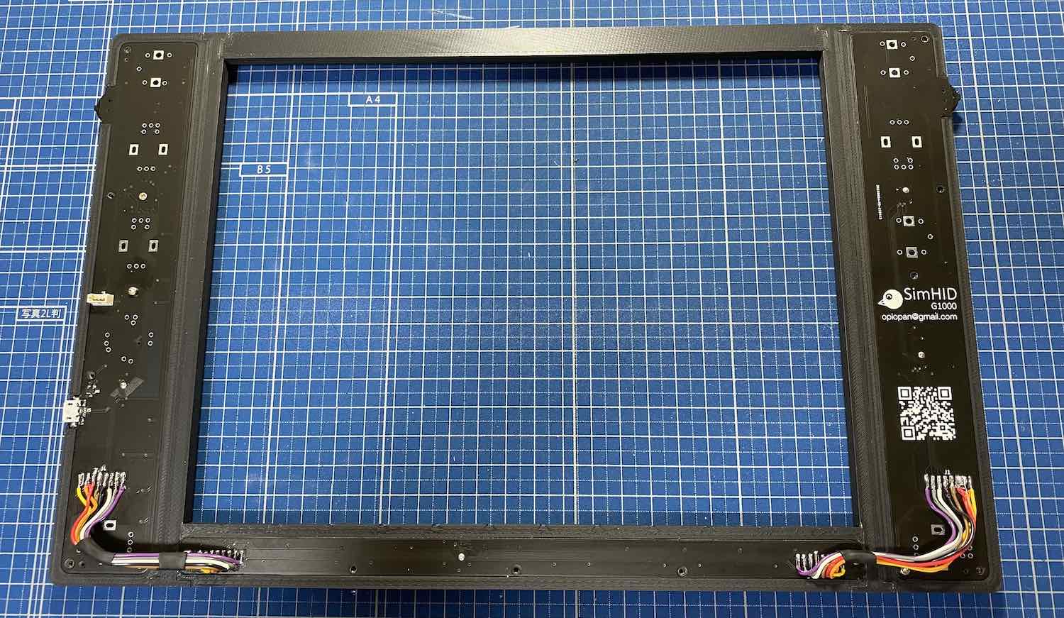
Each PCB are connected to adjacent PCB via the 8 pads junction for interconnect, that are J2, J3, J4 and J5.
It is recommended to solder the interconnect with the PCBs fixed to the front housing of SimHID G1000 in order to properly adjust the length of the wires connecting between PCBs as below.


