We are students in the computer science department at University of Massachusetts Boston. The project idea was provided as a part of our course CS410 "An Intro To Software Engineering" conducted by Professor Kenneth Kofi Fletcher(Github @kkfletch). We students have teamed up with the company named @sign to develop this project, more details provided below.
Peer-to-peer communication system to exchange information about the presence of an object and whether a collision has occured with this object. Driving software developed in Java, along with the help of the @sign libraries and API.
Below is the list of required hardware components needed for this project. It is essential to set up the equipment properly.
The resistors and LED lights serve for debugging purposes and thus the project device will work without them. The list below is given in the order of name of part and count:
Raspberry Pi Pico W,1Pico Headers,1Solderless Breadboards (ALT),1PCs Jumper Wires,10Resistors,10(1, 8) Active Buzzer Module,1(1, 16)Collision Sensor,2(1, 9) Passive Buzzer Module,1(2, 35) Infrared Obstacle Avoidance,2(1, 7) Knock sensor Module,2Micro USB cable (able to exchange data),1
OS: Windows 7 upto Windows 10, macOS 10.15 (Catalina) to 13 (Ventura), or any Linux LTS operating system (preferably Ubuntu).
Suggested code editors or IDEs to use:
- Microsoft Visual Studio Code(Overall good).
Extensions that came in handy are:
Pico-W-Go,PlatformIO IDE - Android Studio Dolphin (For Flutter/Dart development).
- JetBrain IntelliJ(for Java) and Pycharm(for Python).
If you intend to develop in Java: Any version of Java JDK LTS from version 8.0 to 17.0, regardless of distribution, will be needed to compile and run "Application.java" file. This program is found in this root directory. Maven is also required for this project, as it is used to recieve data from the @sign server that the Pico W device sends to.
If you intend to develop in Python and Micro Python: The latest version of Python and Python 3 should do just fine. Micro Python is needed in order to code the Pico. The
Pico-W-Goextension available on Microsoft Visual Studio Code is great for connecting to the Pico. If code from Arduino is understood it can be simple to translate to Micro Python.
If you intend to develop a mobile application using Flutter and Dart: Use the latest version of the Flutter SDK. Check out this link for a step by step guide on how to properly set up the SDK on a Windows operating system. The latest version of the Dart SDK should be used. Here is a guide on how to setup Dart.
Part of the goal of our project was to make use of the @sign libraries and API. Specifically for this project we made use of the AtClient, AtSign, KeyBuilders, Keys, Keys.PublicKeys. All these libraries, along with a whole lot more, can be found on the @sign foundation github repository here
Depending on which programming language you choose to use, @sign has you covered with how to get yourself familiar with their modules and libraries. Step-by-step instructions on properly setting up the software environment can be found in this link, published by @sign themselves. Feel free to check it out.
"Sense for a collision and send the data between two atSigns. One atSign will be the device and the other atSign will be displaying the data on an application."
The purpose of this project is to demonstrate secure communication between two devices or two "involved parties" over the internet with the help of @signs. These @signs are the creation of the company called "@sign", which allows their users to create and own an unique identity on the company servers. Think of it like an email address or an online gamertag, which is distinct for every user. Using an @sign will allow the users to communicate with each other through the @sign company servers while maintaining absolute privacy. This privacy is provided due to the @sign company's encryption protocol for data transmission, as the data is encrypted using special public and private keys. It is the public key that is shared among the @signs, which, when validated, will allow the that certain piece of information to be transmitted. This means no sudden advertisements about something which you have been talking about in your text group chats.
That being said, "communication" between @signs is not limited to just text chats or voice calls. These @signs are capable of being installed on IOT devices, allowing the devices to send and receive encrypted data over the internet. IOT stands for Internet Of Things, where a device is built using
a combination of sensors that only serves to send and receive certain forms(s) of data while connected to the internet. Other than the listed parts mentioned above, there is a large variety of sensors available for anyone to purchase and start builing their own IOT device. Example uses of IOT devices include how a hospital nurse can be paged directly from the front desk, or a doctor directly receiving heart-rate data from a patient using an IOT device to measure the heart-rate etc.
For this project, we have joined together and developed an @sign IOT device. The objective of this project was that our device needs to be
capable of sensing the presence of an object or "obstacle" in it's vicinity. Furthermore, our device should also be able to detect when a collision has
occured with this "obstacle".
The two devices (or people behind the scene) are one in possession of the Pico device and another person on a Windows or Mac or Linux based computer running the "Application.java" program. Both need to be connected to the internet for this project to work. The Pico device will send a "message" to this computer about the presence of the obstacle and collision detection through the onboarded @sign.
Due to it's small size and scale, along with it being very light weight, our project IOT device can be physically installed and embedded onto remote controllable devices, such as drones and robots. This will allow the controller, and the robots themselves, to know about collisions and avoid potentially damaging the operational device or any of its parts. Thus, this can be installed on drones that can be sent out for explorations. Maybe sometime in the future it'll be used on robots sent out for interplanetary explorations, but for now we will stick to Earth.
We recieved the resistors, LEDS, jumper cables (wires), 2 Infrared Obstacle Avoidance sensors, 2 Knock sensor Modules, 1 Passive Buzzer Module, 1 Active Buzzer Module and 2 Collision Sensors. We also recieved a breadboard and the Raspberry Pi Pico. We wanted to put all the sensors together so I (Ronaldo) got another breadboard and more wires so that all the sensors could be connected to the pico. I (Ronaldo) used to be a Computer Engineering major so I had those parts laying around. If you, any one reading this, wants to connect all sensors you will need another breadboard and more wires.
To Begin setting up:
Image Source
The image above is a raspberry pi pico. We can see the pins for it are not connected. Unfortunately that means it needs to be soldered. It is not the easiest thing to do. If anyone can find a way to get the pins on the pico working without soldering be my guest. I (Ronaldo) have found it hard to get devices like the pico to work properly without soldering. I knew someone who knew how to solder and they soldered the board for us. Next step is to put it on our breadboard.
Image Source
The breadboard is shown above. The pico perfectly fits in the middle from the letters cde and fgh. The pico has 40 pins to we goes into the holes up to the number 20. We also need to mention how the breadboard works. The numbers are the rows and the rows are connected horizontally. For example row 1 A is connected up to row 1 E. Row 1 A is not connected to row 2 A. If you put a wire between those then they would be connected. Another thing to mention is the rails on the side with the + and -. The + denotes a voltage in and the red line means that all those holes are connected. The - denotes ground and the blue line mean all the holes next to it are all connected. These rails are very useful because they provide easy access of voltage in and ground. Now we need to start connecting all the sensors.
The resistors and LEDS that were provided were to be used for debugging. We did not use them at all. Just letting you know that if you needed to use the LEDs you would need the resistor otherwise the LED would burn out. The buzzer that was given to us was a good debugger.
We should first discuss how these connections will happen.
Image Source
This shows how the pico is set up. It looks complicated but it is not. The GP pins are basically the ones we use. There is more specific things about each pins but we do not need to worry about the details. We have 4 components so lets just use 4 pins. We can use GP0 to GP3. We should use the VBUS pin as well because the contains the voltage for each component. We should also use GND which is ground so that we can ground the components. Any GND should be fine. We plug in wires in the breadboard row associated with those pins.
So first let us start with the ir sensor (Infrared Obstacle Avoidance sensors).
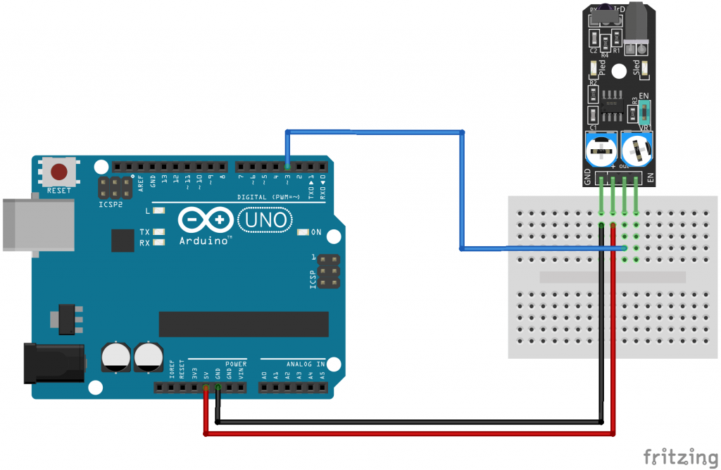
Image Source
This is the setup with arduino using the same sensor we have but it is easy to follow. The red wire is the voltage in so you connect it to the pin that voltage. You can connect it to the rail which you should have connected with the wire connected to the VBUS pin on the pico. The black wire is ground. The blue wire is one of the GP pins. We can connect it to any GP pin. We do not need to worry about the 4th pin. Do not plug anything into it.
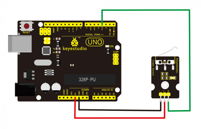
Now the Crash Sensor.
Image Source
Again this has 3 pins. 1 is the voltage in and the other in ground. The last pin again will be connected to a GP pin.
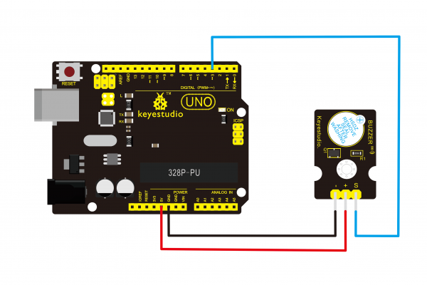
Now the Buzzer.
Image Source
Again this has 3 pins. 1 is the voltage in and the other in ground. The last pin again will be connected to a GP pin.
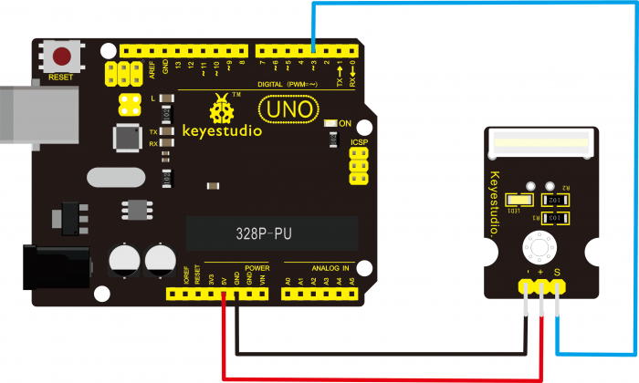
Lastly the Knock Sensor.
Image Source
Once again this has 3 pins. 1 is the voltage in and the other in ground. The last pin again will be connected to a GP pin.
Again, all those voltage in and grounds can be connected to the rails and the rest are connected to the GP pins on the pico.
Hopefully by the end of it, it looks like this.
Source is my (Ronaldo) own picture of how we put our components together.
To explain this, the four sensors are connected. We can see the red wire which is voltage in connected with rails. The black wire next to it is also connected to the rails. Looking closely at the pico, We can see the GP pins I am using are GP0, 1, 2 and 16. GP0 is connected to the crash sensor. GP1 is connected to the buzzer. GP2 is connected to the IR sensor. GP16 is connected to the knock sensor.
Now lets go through some example code.
int buzzPin =  3;    //Connect Buzzer on Digital Pin3
void setup()
{
  pinMode(buzzPin, OUTPUT);
}
 void loop()
{
  digitalWrite(buzzPin, HIGH);
  delay(1000);
  digitalWrite(buzzPin, LOW);
  delay(1000);
}
What this is saying is that the buzzer is connected to pin 3 on the Arduino. The setup is setting the buzzers pin as an output pin. The loop is like a while true and is basically saying to set the buzzer to high which means turn it on. The delay is delaying it by a millisecond. Then it sets the buzzer to low which turns it off.
Now we want to use micropython to code for the pico. We basically translating the arduino CPP code into python.
import machine
import time

buzzer = machine.Pin(3, machine.Pin.OUT) # 3 is the GP1 pin on the pico. It is an output pin because the buzzer makes sound.

while True:
   buzzer.high()
   time.sleep(1)
   buzzer.low()
   time.sleep(1)
This is doing the same as the arduino code. Most code you will find online for components like sensors will be in arduino so knowing how to translate is helpful.
Some notes about the sensors:
- The knock sensor does not stay on long enough for it to be detected. If you try to debug and print out "knock detected" it will not output. The sensor works because its LED will turn on it when you hit it but it does not output because it does it so fast.
- The IR sensor has 2 potentiometer on it. Those are basically resistors that have a knob you can turn to change the resistance. This change in resistance changes the distance that the ir sensor can detect. You can change it so something has to be really close to be detected or further away.
- Lastly, a warning on the buzzer. There are 2 we are given which are a passive one and an active. The active one is VERY LOUD. It startled me (Ronaldo) when I first heard it. The passive buzzer produces a small buzz and is much quieter. I would recommend using the passive one only.
- Ensure that you are upto date on your Windows/Mac/Linux operating system.
- Make sure that your internet connection is stable. Try watching
ONEYouTube shorts video. - Ensure that your Java jdk library are properly installed and upto date, try to make a "Hello World!" program and feel like a god tier coder! jk.
- If you wish to run our version of the project as it is, all you need to do is have Java JDK.
- If you are intending to write your own fucntional code in Python or Flutter/Dart, make sure to clone clone the @sign library for those languages and properly import them into your application file. Python/MicroPython libraries can be found @ this, while for Flutter/Dart look @ here. [see what I did there >_<]
Two operational computer systems, any OS is fine.
On one computer, we need to verify stable internet connection.
Make sure that your firewall allows the device to access the internet through the connected computer.
After the device has been set up properly, it has to be connected to this first computer. We need to make sure we have a micro usb cable that is able to send data.
Depending on which code editor you use, you first upload the code found in "CrashData Send" on the Pico W device. This is easiest with
Pico-W-Goas you can simply just click upload project and it uploads to the pico.
After that is complete, you are to run the "Application.java" file found in the root directory of this repository. This java file will display a GUI. It allows us to choose which sensor data we want to see. Since we can only see the ir obstacle sensor and the crash sensor we will see data from those.
With a stable internet connection and an @sign onboarded onto the Pico W device, the device will now be able to send out data when it will detect an object in its proximity and also send a message when a collision has taken place. In the GUI when we choose which data we want to see, each one shows different results. Obstacle detection will count how many seconds we see the object. Crash detection will count how times the crash sensor was hit. It will save that value even when we change the mode.
[Optional] You can choose to create your very own @sign and give our project a try! Instructions can be found here.
Config logs generated by VS code when compiling and running the Application.java program
Code written in java that recieves the data from the pico which was sent in the python file in CrashDataSend. This also contains or App to display the data in a GUI.
Back-end program which allows data, in our case is information about a crash, to be sent through the @sign servers between @signs
Code for debugging and testing of the components used in the project.
Java code to test the functionality of the Pico W when it comes to receiving data from the @sign servers
Please just go along with the name. It's a collection of the failed attempts in creating a flutter/dart application based @sign API for our project. It also contained the clones of "atmosphere_pro", found here and "atmosphere", found here repositories. There repositories were mainly clones to be looked at how the @sign API was implemented and used in the creation of mobile applications.
Lots of thanks to professor Fletcher, Umass Boston CS department and the @sign team!


