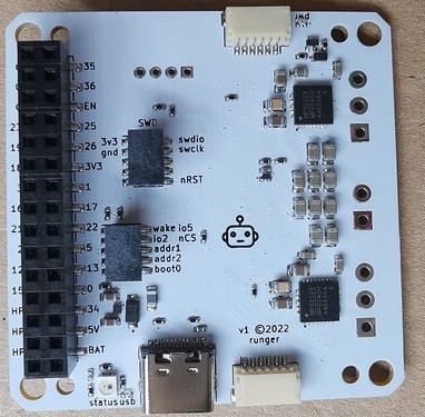
Design for Rosmo ESC - in M5Stack format.
- Dual brushless motor ESC in M5-Stack module format
- Drives 2x 3-phase BLDC motors with up to 40V and 5A (cooling needed - to be tested)
- 2x SPI sensors supported, such as MA732, MA730, AS5048A, AS5047, etc...
- Control inputs via SPI, I2C (and GPIO:question:)
- Grove port for I2C input/output
At the moment, schematic is complete and board has been routed. The BOM is complete but my have to change due to component availability.
Do not use this for anything yet!
Prototype pinout, based on STM32G491MET6, which is probably not the final MCU for this design, but a suitable (if maybe overpowered and therefore expensive) one that was available in the current semiconductor shortage. This MCU is 12x12mm LQFP-80, which is more than enough pins.
Functionality supported by this pinout:
- 2x 3-phase BLDC motor control with 6 PWM (6 outputs on TIM1 and 6 on TIM8, in CHx/CHxN configuration)
- 2x nSLEEP outputs (GPIO)
- 2x nFAULT inputs (interrupt GPIO)
- 2x 3-phase low-side current sensing (6 single-ended inputs on ADC1)
- 1x battery voltage monitor (1 single-ended input on ADC2)
- 3x SPI w/ hardware NSS pin (2 sensor ports + M5 stack SPI pins)
- 2x I2C (grove port + M5 stack SPI)
- USB FS connected to USB-C port (should allow serial monitor function and DFU firmware flashing)
- WAKE input (M5 GPIO connected to system wake 1, so M5 ESP32 can wake STM32 from sleep)
- SWD debug pins connected to standard ARM-10 debug header
- LED pin connected to status LED (or NeoPixel LED)
- BOOT0, nRST, OSC_IN - STM32 system pins
The design uses various custom symbols and footprints. They should load from the project-internal cache when you open the project. If they do not, you can find a kicad library here which contains all the symbols/footprints used, among others.
Uses KiCad 6.


