Skip to content

Latest commit


History

History
237 lines (210 loc) · 11.8 KB

readmeEnglish.md

File metadata and controls

237 lines (210 loc) · 11.8 KB

Test VGA ESP32

Test the video modes in ESP32 from the menu using the PS/2 keyboard or remote keyboard via terminal, such as Putty.
Select the video mode with the up and down arrow keys and press ENTER to accept.

  • 360x200x70hz bitluni
  • 320x240x60hz bitluni
  • 320x240x60hz fabgl
  • QVGA 320x240x60hz fabgl
  • 320x200x70hz bitluni
  • 320x200x70hz fabgl
  • 360x400x70.4hz bitluni
  • 400x300x56.2hz bitluni
  • 320x350x70hz bitluni
  • 320x400x70hz bitluni
  • 640x400x70hz bitluni
  • TTGOVGA32 PAL CVBS 5V (PAL CVBS GPIO 26)
  • TTGOVGA32 PAL CVBS 5V+ (PAL CVBS GPIO 26)
  • ESP32 PAL CVBS 3V (PAL CVBS GPIO 26)
  • TTGOVGA32 NTSC CVBS 5V (NTSC CVBS GPIO 26)
  • TTGOVGA32 NTSC CVBS 5V+ (NTSC CVBS GPIO 26)
  • ESP32 NTSC CVBS 3V (NTSC CVBS GPIO 26)
  • 320x240x60hz bitluni PLL
  • 320x200x70hz bitluni PLL
  • 384x264x56.2hz bitluni
  • 360x240x56.3hz bitluni
  • T40x25 320x200x70 bitluni
  • T40x30 320x240x60 bitluni
  • T50x37 400x300x56.2 bitlun
  • T80x50 640x400x70 bitluni
  • T80x25 640x400x70 bitluni
  • T40x25x3 320x200x70 bitlun
  • T40x30x3 320x240x60 bitlun
  • T50x37x3 400x300x56.2 bitl
  • T80x50x3 640x400x70 bitlun
  • T80x60x3 640x480x70 bitlun
  • T80x25x3 640x400x70 bitlun
  • 320x200x1x70Hz bitluni
  • 320x240x1x60Hz bitluni
  • 400x300x1x56.2hz bitluni
  • 640x400x1x70hz bitluni
  • 800x600x1x54.2hz bitluni
  • PIC 250 GTO
  • PIC Phantis
  • PIC Game Over
  • PIC Mandril


Pre-compiled version

In the precompile folder there are several versions already compiled to be able to be recorded with the flash download tool 3.9.2.

https://github.com/rpsubc8/ESP32TestVGA/tree/main/ESP32/precompile

We must choose the ESP32 type:

Subsequently, select the files as shown in the attached screenshot, with the same offset values:

And press start. If everything has been correct, we will only have to restart the ESP32.


Requirements

Required:
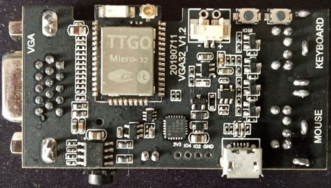
  • TTGO VGA32 v1.x (1.0, 1.1, 1.2, 1.4)
  • Visual Studio 1.66.1 PLATFORMIO 2.5.0 Espressif32 v3.5.0
  • Arduino IDE 1.8.11
  • Arduino bitluni 0.3.3 (Ricardo Massaro) reduced library (included in project)


ArduinoDroid

You must run, just once, the script makeandroid.bat, which leaves the entire data structure of the dataFlash directory in the root directory, as well as replacing the main files with .h calls without using the dataFlash data directory.
At the end, the script itself ends up deleting the dataFlash directory.
The script uses fart.exe (find and replace text).
Once, it has been successfully executed, it can be used with the ArduinoDroid.


Arduino Web Editor

The makeandroid.bat script must be run once only. Once finished, it is uploaded to the cloud as any other project, either compressed in zip or by files.


PlatformIO

PLATFORMIO 2.5.0 must be installed from the Visual Studio extensions. Espressif32 v3.5.0 is also required.

Then the working directory testvga will be selected. We must modify the platformio.ini file the upload_port option to select the COM port where we have our TTGO VGA32 board, if for some reason it is not detected by us.

Then we will proceed to compile and upload to the board. No partitions are used, so we must upload the entire compiled binary. It is all set up so you don't have to install the bitluni and fabgl libraries.


Arduino IDE

The whole project is compatible with the Arduino 1.8.11 framework. We only have to open the testvga.ino from the testvga directory.

We must install the spressif extensions in the additional card url manager https://dl.espressif.com/dl/package_esp32_index.json.
The project is now ready, so no bitluni or fabgl libraries are needed. We must deactivate the PSRAM option, and in case of exceeding 1 MB of binary, select 4 MB of partition when uploading. Although the code does not use PSRAM, if the option is active and our ESP32 does not have it, an exception will be generated and it will restart in loop mode.


Test keyboard PS/2

To test a PS/2 keyboard:

https://github.com/rpsubc8/testkeyboardPS2


UART keyboard

If the option use_lib_keyboard_uart is activated, it allows to use the PC keyboard from the VStudio monitor or from the putty (115200 bauds), in a simple way, since it is not by reading SCANCODE down, up:
  • TAB key or F2 key: Display OSD
  • ENTER: Send ENTER (accept)
  • Up: Up (increment 1)
  • Down: Down (drecement 1)
  • Right: Right (increment 10)
  • Left: Left (decrement 10)
From the Arduino IDE, this functionality is not allowed, since the serial monitor requires sending the ENTER for each action.


Options

The gbConfig.h file options are selected:
  • use_lib_log_serial: Logs are sent by usb serial port
  • use_lib_keyboard_poll_milis: The number of polling milliseconds for the keyboard must be specified.
  • use_lib_fix_double_precision It doesn't use the VGA video frequency calculation with the ESP32 itself, avoiding possible accuracy problems with the mantissa. This is useful for ESP32's that miscalculate the frequency.
  • use_lib_debug_i2s Plot with video mode calculations.
  • use_lib_vga360x200x70hz_bitluni 360x200 video mode with bitluni parameters.
  • use_lib_vga320x200x70hz_bitluni 320x200 video mode with bitluni parameters.
  • use_lib_vga320x200x70hz_fabgl 320x200 mode with fabgl parameters.
  • use_lib_keyboard_uart: Allows you to use the PC keyboard from the PC via the VStudio monitor terminal or from putty, without having to have a keyboard. Useful for not having to use the physical PS/2 keyboard and for development.


DIY circuit

If we don't want to use a TTGO VGA32 v1.x board, we can build it following the fabgl schematic:

In the case of wanting cvbs video output, instead of VGA, we must take a direct cable from pin 26 of the PS/2 connector of the mouse, activating the option use_lib_cvbs_pal, as well as use_lib_cvbs_ttgo_vga32 of the gbConfig.h. If we do not activate this option, the output will be more than 1 volt, having to be reduced with a voltage reducer (potentiometer).

The PS/2 connector is seen from the board's own jack, that is, the female jack. The pin on PS/2 is CLK, that is, 5.

In this image you can see the internal SOT23 mosfet of the TTGO VGA32 board, so that the output at CLK (pin 5) is 5 volts.


Test DAC cvbs

For TTGO VGA32 as the output is 5v, either we do voltage reduction or we can reduce the scale of the DAC. At 3.3v output, with a maximum value of 77, it would already give us 0.99v, which would be 1v. If we have 5v output, with 50, we already have 0.97v, which would be 1v. In this way, we no longer need step-down resistors, it is the direct wire. As long as we don't go over 77 in 3.3v or 50 in 5v, we won't have a problem, especially if we only need 2 colors (black and white). We can do tests with a multimeter, especially on the TTGO VGA32 v1.x:
//ESP32 Pin 26
//DAC - Voltaje
//  0 - 0.06
// 38 - 0.52
// 77 - 1
//255 - 3.17

#include <Arduino.h> #include <driver/dac.h>

const int arrayValue[4]={0,38,77,255}; unsigned char cont=0;

void setup() { Serial.begin(115200); dac_output_enable(DAC_CHANNEL_2); }

void loop() { dac_output_voltage(DAC_CHANNEL_2, arrayValue[cont]); Serial.printf("%d\n",arrayValue[cont]); delay(4000); cont++; cont &= 0x03; }

The maximum values when writing to the video buffer on an ESP32 board is 54, while for TTGO VGA32 v1.x it would be 35.


Monochrome (8 colours)

In the classical era, black and white monitors were used, so that more benefit was gained from colour. By applying a basic greyscale filter the same effect can be achieved, with only 8 colours and the basic 3-bit DAC.
I have created a tool to convert the 8-colour palette in 3-bit DAC mode (RGB) to a monochrome gradient. Here you can see a model car of the Ferrari 250 GTO with the 8 colours:

And here activating the greyscale filter with 8 gradients:

The filter can be easily achieved with a monochrome VGA monitor.
On modern monitors and TVs, if they have filters in the OSD, this is also very simple. If not, you can vary the values of each RGB component from the OSD to achieve saturation.
If you have a VGA capture machine, you can apply the filter from within Windows by activating the saturation.

If we set the digital vibrance of 50 to a value of 0, we are left with black and white.


Here is the DAC 3-bit 8-colour palette with its decimal and binary (RGB) value:

Here it is, as seen from a monochrome monitor:

As can be seen, the logical order does not correspond to the actual order of light. For that, if we apply an order by luminance:

This order, is what is applied to the image internally, so that you can actually see the 8 grey gradients, so the order is:
  • 0 - 0
  • 1 - 4
  • 2 - 1
  • 3 - 5
  • 4 - 2
  • 5 - 6
  • 6 - 3
  • 7 - 7

To process the images, we have to convert them to greyscale (256 gradients) from Gimp or Paint Shop Pro, and then apply the 8-colour grey gradient reduction:

We must make sure that we have 8 colours left, even if we are using image formats with 16.

And finally a conversion to RAW is applied.
When viewing, the above order should be applied.

Here we have the Phantis with 8 colours:

And here in monochrome:

Here is the GameOver with 8 colours:

And here in monochrome:

EGA and VGA test chuck with 8 colours:

And here in monochrome: