-
Notifications
You must be signed in to change notification settings - Fork 120
Home
XIVO is a filtering-based visual-inertial odometry (VIO) system. At its core, XIVO is an Extended Kalman Filter (EKF) with additional image processing and mapping capabilities. A diagram of its components is shown below.
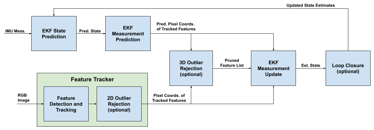
IMU measurements are implemented as model inputs. EKF State Prediction occurs whenever a new IMU measurement is acquired, typically at a frequency of hundreds of Hz. Pixel coordinates of tracked features are sensor measurements. EKF Measurement Prediction, Image Processing, and EKF Measurement Update occur whenever a new RGB image is acquired, typically at a frequency of dozens of Hz. Mapping searches for loop closures and solves the bundle adjustment problem in the background.
- Spatial/world frame
s- A static frame that is never moving. For issues related to observability, it is fixed to be the position and orientation of the IMU at startup. - Body/IMU frame
b- A frame attached to the IMU. The exact direction of the axes are determined by the manufacturer and how the IMU is mounted. - Camera frame
c- A frame attached to the camera's pinhole. TheZaxis points outward perpendicular to the image plane. TheXaxis points horizontally to the right side of the image plane. TheYaxis completes the triad, i.e. theYaxis points down. - Pixel frame
p- A 2D frame whose origin is the top-left corner of the image. The projection operator and the camera intrinsics map points in thecframe with units of meters to points in thepframe with units of pixels. - Gravity frame
g- A frame that is aligned with gravity and co-located with thebframe. In this frame, gravitational acceleration has value[0, 0, -9.8].
XIVO's map is a collection of point features (e.g. SIFT, FAST, BRISK, ORB) detected and tracked over multiple images and groups organized into a graph, pictured below.
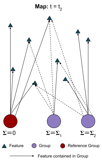
In the context of XIVO's map, a group is the position of the robot at an instance in time when an image was received, i.e. the rotation and translation that describes the pose of the b frame relative to the s frame at an instance in time when an image was received. A directed edge from a group to a feature means that the feature was visible in the image associated with the group. The position and covariance of both features and groups are estimated in the EKF. Two groups are co-visible if they both contain an edge to the same feature. For reasons related to observability, one group, designated the Reference Group or Gauge Group, is fixed -- the filter estimates positions and orientations relative to relative to the Reference Group until co-visibility with the Reference Group is lost -- there is therefore no uncertainty in the position of the Reference Group.
When co-visibility with the Reference Group is lost, the co-visible group with the smallest covariance is fixed as the new Reference Group:
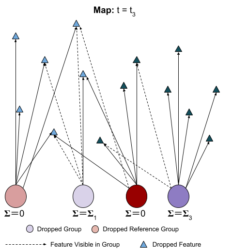
This second Reference Group's position relative to the original Reference becomes a fixed value in the state estimation algorithm.
The state of a tracked feature, from birth to death, is shown below.
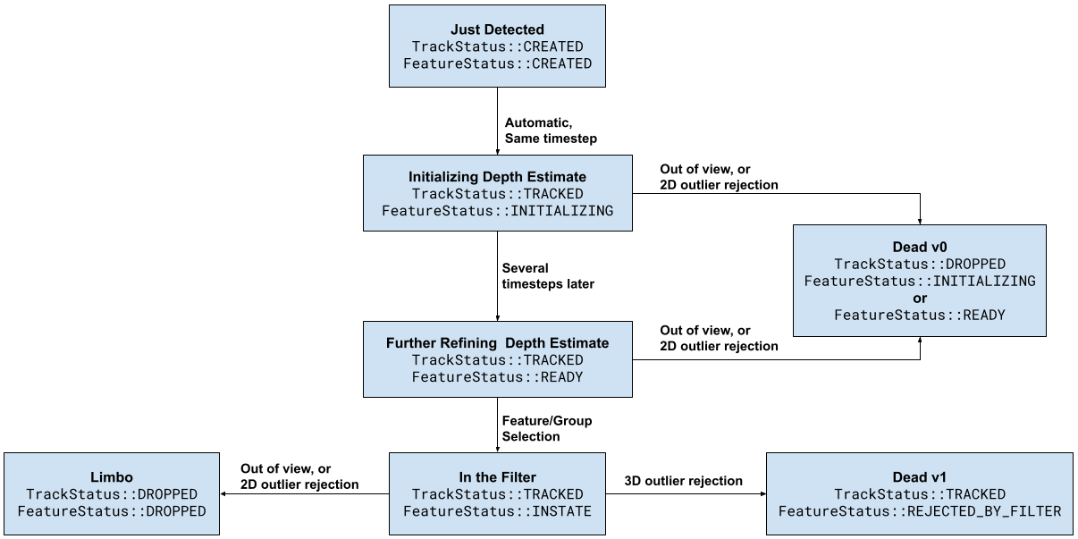
Tracked features are 2D points located in multiple images. However, the EKF needs to maintain an estimate of the feature's 3D location. Therefore, we wait until the feature has been successfully tracked by the subfilter for subfilter.ready_steps frames (a parameter in a Configuration File) in an initialization phase before incorporating it into the EKF. During this phase, a subfilter and triangulation is used to estimate the feature's depth. This depth estimate is then used as the initial value of the feature's position in the filter.
A feature will "die" if the feature tracker loses track (presumably because it goes out of view) and if it is marked an outlier. Features in Limbo will be used to search for loop closures and solve bundle adjustment. If using MSCKF measurement updates (optional), features in transition to Limbo or Dead v0 provide one-time measurement updates.
Please see our equations document for a detailed description.
Upon receiving the first image, XIVO's feature detector detects at least tracker_cfg.num_features_min and up to tracker_cfg.num_features_max features. In subsequent frames, the Tracker uses Lucas-Kanade Optical Flow to search for features already existing in the last frame. Features that go out of view are marked as TrackStatus::DROPPED. New features are then detected to replace any dropped features.
Please see our equations document for a detailed description.
XIVO uses Mahalanobis Gating and One-Pt RANSAC to reject outlier tracks produced by image processing. Both components are optional. If using both, One-Pt RANSAC is performed after Mahalanobis Gating.
In Mahalanobis Gating, features with a Mahalanobis Distance greater than MH_thresh (a configuration parameter) are rejected. In the event that the number of tracked features is very small (less than the configuration parameter min_inliers), MH_thresh can be iteratively multiplied by a factor of MH_adjust_factor (a configuration parameter >= 1.0) until the number of tracked features is equal to min_inliers.
(Coming soon.)
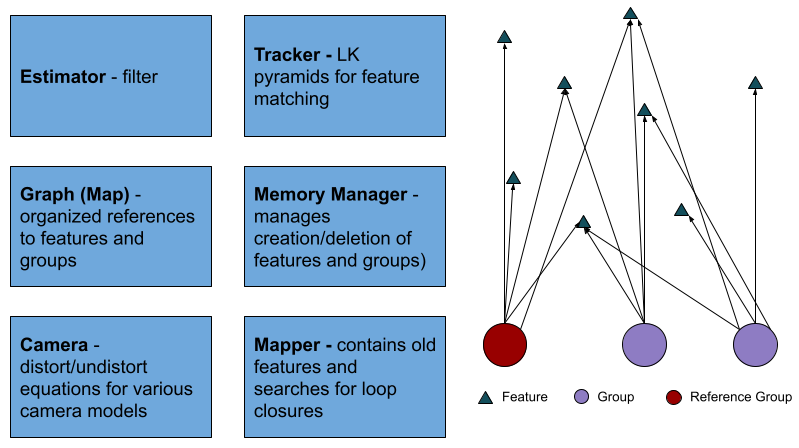
Xivo is implemented in C++ in an object-oriented paradigm. A list of objects is shown below. Major components, shown in blue boxes, are singletons. The map is a collection of Feature and Group (past poses at times RGB images were taken) objects created by the MemoryManager and accessible through the Graph. Feature and Group objects are not contained within any of the singletons, but are designed to be accessed through the Graph object.
